diy solar

diy solar

JK BMS CAN bus comms now possible for inverters that support Goodwe and Pylontech batteries

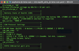
In the YAML, the default protocol is 1, you must define protocol 2 to send ID 0x379 for Luxpower (battery capacity).
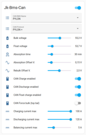
That's exactly what I have configured, here is my deployed YAML:
Screenshot 2024-02-06 at 9.06.02 AM.png

Also note that I can't get the device to respect my absorption settings and time to get my batteries balanced above 3.45. It hits absorption voltage and swings right back to discharge.
 
That's exactly what I have configured, here is my deployed YAML:
View attachment 193800

Also note that I can't get the device to respect my absorption settings and time to get my batteries balanced above 3.45. It hits absorption voltage and swings right back to discharge.

CAN settings are OK but maybe your inverter model uses a different ID for battery capacity. I understand that you use an EG4 which is built by Luxpower?

The end of charge settings are different for each inverter. Calibration of the inverter and BMS voltages is necessary for correct operation. If you have kept the default values, the absorption phase (timer 30min) will only begin if the BMS voltage (not that of the inverter) is >= (Bulk V. - 0.05V) therefore 55.15V by default .

If I keep the default settings, it doesn't work with my Deye.
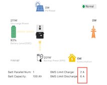
I upgraded to .4 version of your code. The charge/discharge amps are not showing correctly. After update I changed inverter battery from 0 to 2 and now it’s reading total ah correctly but the charge and discharge amps are showing wrong on both battery settings (set to 20a charge and 60a charge in YAML).
IMG_4552.jpeg
 
I upgraded to .4 version of your code. The charge/discharge amps are not showing correctly. After update I changed inverter battery from 0 to 2 and now it’s reading total ah correctly but the charge and discharge amps are showing wrong on both battery settings (set to 20a charge and 60a charge in YAML).
View attachment 193838

Charge and discharge amps are sent with ID 0x351 for all CAN protocol types and there has been no change in the format of what is sent between 1.16.3 and 1.16.4.

How did you configure your inverter?
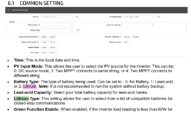
Battery type: 2
Lithium type: what choice do you have?

1707243656765.png
 
Charge and discharge amps are sent with ID 0x351 for all CAN protocol types and there has been no change in the format of what is sent between 1.16.3 and 1.16.4.

How did you configure your inverter?
Battery type: 2
Lithium type: what choice do you have?

View attachment 193888
I have it set to Lithium and Battery type 2 (Pylon) and battery capacity is now accurate. I think it’s a weird UI problem in the EG4 app. On the website it shows the correct charge and discharge amps from the YAML.

Still need to work on absorption and float settings. Something odd there where it’s not going through the 30 minute absorb cycle.
 
Still need to work on absorption and float settings. Something odd there where it’s not going through the 30 minute absorb cycle.

See this comment

Inverter and BMS Voltage calibration + test with different Absorption Offset V.

For information here is what I use with Deye.

YAML:
# +--------------------------------------+
# | Battery Charge Settings              |
# +--------------------------------------+
# This is max charging amps eg 100A, for Bulk - Constant Current charging(CC), should be at least 10A less than BMS change current protection, 0.5C max
# 100A * 50V = 5000W
  charge_a: "100"
# Float Voltage : corresponds to the voltage at which the battery would be maintained at the end of the absorption phase. (53.6v eg 3.35v/cell for 16 cells 48V battery)
  float_v: "53.7"
# Absorption Voltage : corresponds to the Bulk voltage that will be used to charge the battery. (55.2v eg 3.45v/cell for 16 cells 48V battery)
  absorption_v: "55.3"
# Absorption time in minutes to hold charge voltage after charge voltage is reached eg 30
  absorption_time: "30"
# Absorption offset, x Volts below absorption voltage battery will start the absorption timer, eg 55.2-0.05 = 52.15v
  absorption_offset_v: "0.15"
# Rebulk offset, x Volts below absorption voltage battery will request rebulk, eg 55.2-2.5 = 52.7v
  rebulk_offset_v: "2.5"
 
Thanks @Sleeper85, still testing. I increased by absorption timer to .20 to see what happens, charging now.
Separate question. If I have 4 of the same batteries/bms config in parallel and set the parameters that way (e.g. battery count=4 in yaml) is it safe to assume this one esphome device will be able to effectively 'control' all packs, understand there is no direct connection to the other BMSs.

 
Charging update: seems when AC charging, it is not using the project parameters. It gets to 100% SOC and simply switches to discharge, no absorption or float.

I fully understand this project only works with one BMS. I’m making an assumption if I have 4 identical 48v packs in parallel, each with their own BMS and ONLY one connected to the inverter with this project, in theory SOC measurements, charging and discharging could still be managed by the one connected BMS passively for all packs.

Anyway just a theory and a lot could go wrong with this. This project is awesome and will keep testing.
I use an earlier forked version of the uksa007 code with different logic that acts similar to the smart shunt (terminate charging based on tail current, time, etc).
My Solis inverter stops charging when the BMS reads 100%, regardless of the battery voltage.
In my case, I set the max SOC sent from the ESP32 to 97% unless the charge termination conditions were reached, at which point the 100% from the BMS is sent.

It might be that something similar is needed for your setup.
 
@ChrisG @MrPablo

Indeed, some inverters like Sofar, etc. stops charging as soon as the SoC is 100%. So this is a problem if JK-BMS sends 100% SoC and the battery is not fully charged.

So I think I could modify the script to send 100% only at the end of the absorption phase.
 
V1.16.5 the new Balancing function is still in the testing phase
V1.16.6 Improvement of CAN ID 0x355, sending 100% only at the end of the absorption phase, adding bytes [04:05] and [06:07]

@tonystrullu @ChrisG @MrPablo

Here is what I suggest as code regarding ID 0x355 and sending the SOC.

C++:
// Byte [00:01] : State of Charge (SOC)    (1 %)
// Byte [02:03] : State of Health (SOH)    (1 %)
// Byte [04:05] : SOC high resolution      (0.01 %)
// Byte [06:07] : Remaining total capacity (1 Ah) (Sofar)

uint8_t can_mesg[8];
uint16_t soc;
uint16_t soh;

// SOC - Sending 100% only at the end of the absorption phase
if (id(state_of_charge).state < 100) soc = id(state_of_charge).state;       // SOC < 100% => Sending BMS SOC
else if (id(eoc) == true) soc = 100;                                        // End Of Charge => Sending 100%
else soc = 99;                                                              // Otherwise => Sending 99%

// SOH
soh = round(((id(charging_cycles).state/${max_cycles})-1)*-100);

can_mesg[0] = soc & 0xff;
can_mesg[1] = soc >> 8 & 0xff;
can_mesg[2] = soh & 0xff;
can_mesg[3] = soh >> 8 & 0xff;
can_mesg[4] = (soc * 100) & 0xff;
can_mesg[5] = (soc * 100) >> 8 & 0xff;
can_mesg[6] = uint16_t(id(capacity_remaining_ah).state * 10) & 0xff;
can_mesg[7] = uint16_t(id(capacity_remaining_ah).state * 10) >> 8 & 0xff;
ESP_LOGI("main", "send can id: 0x355 hex: %x %x %x %x %x %x %x %x", can_mesg[0], can_mesg[1], can_mesg[2], can_mesg[3], can_mesg[4], can_mesg[5], can_mesg[6], can_mesg[7]);
return {can_mesg[0], can_mesg[1], can_mesg[2], can_mesg[3], can_mesg[4], can_mesg[5], can_mesg[6], can_mesg[7]};
 
Last edited:
V1.16.5 the new Balancing function is still in the testing phase
V1.16.6 Improvement of CAN ID 0x355, sending 100% only at the end of the absorption phase, adding bytes [04:05] and [06:07]

@tonystrullu @ChrisG @MrPablo

Here is what I suggest as code regarding ID 0x355 and sending the SOC.

C++:
// Byte [00:01] : State of Charge (SOC)    (1 %)
// Byte [02:03] : State of Health (SOH)    (1 %)
// Byte [04:05] : SOC high resolution      (0.01 %)
// Byte [06:07] : Remaining total capacity (1 Ah) (Sofar)

uint8_t can_mesg[8];
uint16_t soc;
uint16_t soh;

// SOC - Sending 100% only at the end of the absorption phase
if (id(state_of_charge).state < 100){ 
  soc = id(state_of_charge).state;       // SOC < 100% => Sending BMS SOC
}
else if (id(eoc) == true){ 
  soc = 100;                             // End Of Charge => Sending 100%
}
else { 
  soc = 99;                              // Otherwise => Sending 99%
}
// SOH
soh = round(((id(charging_cycles).state/${max_cycles})-1)*-100);

can_mesg[0] = soc & 0xff;
can_mesg[1] = soc >> 8 & 0xff;
can_mesg[2] = soh & 0xff;
can_mesg[3] = soh >> 8 & 0xff;
can_mesg[4] = (soc * 100) & 0xff;
can_mesg[5] = (soc * 100) >> 8 & 0xff;
can_mesg[6] = uint16_t(id(capacity_remaining_ah).state * 10) & 0xff;
can_mesg[7] = uint16_t(id(capacity_remaining_ah).state * 10) >> 8 & 0xff;
ESP_LOGI("main", "send can id: 0x355 hex: %x %x %x %x %x %x %x %x", can_mesg[0], can_mesg[1], can_mesg[2], can_mesg[3], can_mesg[4], can_mesg[5], can_mesg[6], can_mesg[7]);
return {can_mesg[0], can_mesg[1], can_mesg[2], can_mesg[3], can_mesg[4], can_mesg[5], can_mesg[6], can_mesg[7]};
Seems logical as the 6000xp keep charging right until 100% then starts discharge, will give it more time. I’m rebuilding my packs to 2p16s so i can have more ah and test this out. Should be back up by Saturday.
 
Thanks @Sleeper85!
I have a couple of ideas for dynamic charge voltage and dynamic charge current that I intend to test on a fork of your code. As soon as I'm done, I'll share the results in case you want to pull them in.

Many thanks for all your work on this!
 
Thanks @Sleeper85!
I have a couple of ideas for dynamic charge voltage and dynamic charge current that I intend to test on a fork of your code. As soon as I'm done, I'll share the results in case you want to pull them in.

Many thanks for all your work on this!

@shvm already sent me some code with new charging logic based on tail current etc. (I haven't taken the time to look at it yet).

Maybe you can discuss it together.
 
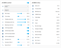
Attached you will find the YAML for V1.16.6 beta.

My tests are OK but I would like to have your feedback before publishing it on GitHub.
There have been a lot of changes since V1.16.4.

I would like to be sure that this version is stable before leaving for my 4 month trip.

So there are two possible scenarios:
  • Bulk > (Absorption or Balancing) > EOC > Float (if switch ON)
  • Force Bulk > Balancing > EOC > Float (if switch ON)
This makes the "Force Bulk" function more secure because it will be automatically deactivated at the end of the Balancing phase and will no longer be able to function indefinitely as before.

Attention ! a BMS alarm always has priority and can stop this process.

Hope it works well for you.

V1.16.6
  • Selectable CAN settings
  • Adding inverter_offset_v (correction of the inverter charging voltage)
  • Improved CAN ID 0x355, sending 100% only at the end of charge (EOC), adding bytes [04:05] and [06:07]
  • Automatic calculation of the number of battery modules ( @ChrisG fewer questions to ask :) )
  • Save and Restore slider values

V1.16.5
  • Add Preventive Alarms Logic and Balancing function
  • CAN ID 0x356: send average temperature of T1/T2
  • New "Discharging current max" and "Balancing current max" slider

HA_Dashboard_JK-BMS-CAN.png


Edit: YAML removed, I'm working on new current based charging logic.
 
Last edited:
For batteries without a BMS with comms, is this able to create a "fake" Canbus BMS to send battery info (perhaps supplied from a SmartShunt via MQTT) to a GoodWe inverter?
 
For batteries without a BMS with comms, is this able to create a "fake" Canbus BMS to send battery info (perhaps supplied from a SmartShunt via MQTT) to a GoodWe inverter?

Nothing is impossible, you just have to do it.
:giggle:
 
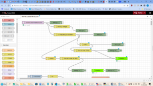
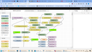
I am not a programmer partly as it bores me to death writing out 40 lines of code to do what I can describe in one sentence. A good 1/2 way house is Node-red which runs on Windows Linux and Raspbian etc


Each node undertakes a task and they are joined graphically on a webpage where you can program each node and join them up into flows and access connected hardware.

Here are a few examples I developed.

There is a few canbus nodes and Modbus


So you could as an example pull in data from Modbus registers and send them out on a canbus or the other way round.
 

Attachments

  • Screenshot (3).png
    Screenshot (3).png
    296.3 KB · Views: 8
  • Screenshot (6).png
    Screenshot (6).png
    427 KB · Views: 8
  • Screenshot (9).png
    Screenshot (9).png
    365.5 KB · Views: 8
Last edited:
I am not a programmer partly as it bores me to death writing out 40 lines of code to do what I can describe in one sentence. A good 1/2 way house is Node-red which runs on Windows Linux and Raspbian etc


Each node undertakes a task and they are joined graphically on a webpage where you can program each node and join them up into flows and access connected hardware.

Here are a few examples I developed.

There is a few canbus nodes and Modbus


So you could as an example pull in data from Modbus registers and send them out on a canbus or the other way round.
But ESP32 can work alone, without WiFi, etc. and this reduces the number of possible problems.
 
But ESP32 can work alone, without WiFi, etc. and this reduces the number of possible problems.
Correct 100% but if you can't program and need a solution that does not currently exist and you don't know Python or another language that runs on an ESP32 then Node-red on a Pi allows you to get a solution.
 
Correct 100% but if you can't program and need a solution that does not currently exist and you don't know Python or another language that runs on an ESP32 then Node-red on a Pi allows you to get a solution.

Yes, I use and love Node-RED ;)
 
Hi All

any one know why we are getting all unknown values even though the CAN is o.k?

View attachment 196537

The Bluetooth code works - suggesting it has to be the GIO Pins wrong, i have tried 16/17 and 01/03 and even swapped them around.

please advise

I have logged 3 issues so far for the developers:

1. CAN wire showing unknown for Sensors that work in the Bluetooth Code
2. Incorrect Resistance calculated by the ESP code (correct in the BMS)
3. Substitution error when removing the esp api to replace with mqtt

hope we sort this out

thanks for the great work...

regards
 
Last edited:

diy solar

diy solar
Back
Top