Thanks, have everything ordered, should have all parts by end of month. Can't wait to give this a shot, just bought some of the older JKs.As written in the readme, JST 1.25mm pitch.
Code:# RS485-TTL jack on JK-BMS (4 Pin, JST 1.25mm pitch) ┌─── ─────── ────┐ │ │ │ O O O O │ │GND RX TX VBAT│ └────────────────┘ │ │ │ | VBAT is full battery volatge eg 51.2V (No connect) │ │ └──── ESP32 GPIO16 (`rx_pin`) │ └──────── ESP32 GPIO17 (`tx_pin`) └──────────── GND


You are using an out of date browser. It may not display this or other websites correctly.
You should upgrade or use an alternative browser.
You should upgrade or use an alternative browser.
JK BMS CAN bus comms now possible for inverters that support Goodwe and Pylontech batteries
- Thread starter uksa007
- Start date
Sleeper85
Sunday handyman
- Joined
- Nov 28, 2022
- Messages
- 443
Thanks, have everything ordered, should have all parts by end of month. Can't wait to give this a shot, just bought some of the older JKs.
You have a Victron system, right?
Pay double attention to the VBAT on the JST JK connector. This is the full voltage of your pack, handle with caution.
Thanks, have everything ordered, should have all parts by end of month. Can't wait to give this a shot, just bought some of the older JKs.
Yes, have one Victron system, also a Growatt and more than likely a EG4 6000XP in my future. Interested in figuring out how they can all talk Pylon. Thanks for the VBAT warning, saw that earlier.You have a Victron system, right?
Pay double attention to the VBAT on the JST JK connector. This is the full voltage of your pack, handle with caution.
Sleeper85
Sunday handyman
- Joined
- Nov 28, 2022
- Messages
- 443
Yes, have one Victron system, also a Growatt and more than likely a EG4 6000XP in my future. Interested in figuring out how they can all talk Pylon. Thanks for the VBAT warning, saw that earlier.
So you will probably be the first to test my YAML with Victron, I will make improvements for Victron before your tests start. I will send you a YAML privately so you can validate that everything is working correctly.
Do you use Home Assistant?
Have you ordered the equipment below?

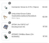
Don't rush on the code, won't have the parts till end of month. I ordered the JST 4 pin 1.25 pitch connectors/wires on amazon and I already have a 5v power block with usbC cable. I'll just solder the jst cable out of JDK to the Unbuckled groove cable. I'll then need the specific pins for the out of the CanBus to the inverter...will look into that later. Here is my order:So you will probably be the first to test my YAML with Victron, I will make improvements for Victron before your tests start. I will send you a YAML privately so you can validate that everything is working correctly.
Do you use Home Assistant?
Have you ordered the equipment below?
View attachment 187903

@Sleeper85, yes I also use Home Assistant and little Node-Red.
Sleeper85
Sunday handyman
- Joined
- Nov 28, 2022
- Messages
- 443
Don't rush on the code, won't have the parts till end of month. I ordered the JST 4 pin 1.25 pitch connectors/wires on amazon and I already have a 5v power block with usbC cable. I'll just solder the jst cable out of JDK to the Unbuckled groove cable. I'll then need the specific pins for the out of the CanBus to the inverter...will look into that later. Here is my order:
Why did you choose this model which does not fit directly onto the pins of the ESP32 Atom Lite?

The base used by @arzaman is this one, I find it more beautiful and cleaner.

Additionally you will need the input port on the Atom Lite to connect the 5V, GND, RX and TX coming from JK-BMS.

Code:
# GPIO pins your CAN bus transceiver ATOMIC CANBus Base (CA-IS3050G)
  can_tx_pin: GPIO22
  can_rx_pin: GPIO19
# GPIO pins your JK-BMS RS485(TTL) is connected to the grove port of ATOM lite
  tx_pin: GPIO32
  rx_pin: GPIO26

  esp32:
  board: m5stack-atom
  framework:
    type: arduino
Last edited:
Hmm. It’s the exact same part number. CAIS3050G. Did I order wrong?Why did you choose this model which does not fit directly onto the pins of the ESP32 Atom Lite?
View attachment 187909
The base used by @arzaman is this one, I find it more beautiful and cleaner.
View attachment 187910
Additionally you will need the input port on the Atom Lite to connect the 5V, GND, RX and TX coming from JK-BMS.
View attachment 187916
Code:# GPIO pins your CAN bus transceiver ATOMIC CANBus Base (CA-IS3050G) can_tx_pin: GPIO22 can_rx_pin: GPIO19 # GPIO pins your JK-BMS RS485(TTL) is connected to the grove port of ATOM lite tx_pin: GPIO32 rx_pin: GPIO26 esp32: board: m5stack-atom framework: type: arduino
Edit: I had to cancel the entire order. Odd the part numbers are identical anyway reordered from M5. Should be here in 30-60 days.
Attachments
Last edited:
arzaman
New Member
- Joined
- Nov 9, 2022
- Messages
- 40
Hmm. It’s the exact same part number. CAIS3050G. Did I order wrong?
Edit: I had to cancel the entire order. Odd the part numbers are identical anyway reordered from M5. Should be here in 30-60 days.
You can't use this module becouse if you use the grove port to connect to Atom (ESP32) yuo don't have any more a socket to conenct JK-BMS RS485 port...unless you use the GPIO on the bottom...so basically the opposite of my implementation
")


Recheck the alarm implementation.V1.15.5 on GitHub
I decided to deactivate the API reboot every 15 minutes if there is no connection with HA, I think we should prevent the ESP32 from rebooting which could happen during a Bulk charge. I also adapted the default discharge current to 120A therefore 6000W.
In addition, as I received a lot of questions regarding the operation of the charging logic I created the diagram below to make it clear.
View attachment 187443
Low voltage alarm should not stop charging.
High voltage alarm should not stop discharging.
Temperature alarm - is ok as it is.
Else if you stop charging at low votge alarm, how will the battery regain charge?
Sleeper85
Sunday handyman
- Joined
- Nov 28, 2022
- Messages
- 443
Recheck the alarm implementation.
Low voltage alarm should not stop charging.
High voltage alarm should not stop discharging.
Temperature alarm - is ok as it is.
Else if you stop charging at low votge alarm, how will the battery regain charge?
OK, I'm preparing version 1.16, I'll add that to my to do list.
I believe I ordered the correct one in my edit above. Yes?You can't use this module becouse if you use the grove port to connect to Atom (ESP32) yuo don't have any more a socket to conenct JK-BMS RS485 port...unless you use the GPIO on the bottom...so basically the opposite of my implementation
View attachment 188038
View attachment 188039
Sleeper85
Sunday handyman
- Joined
- Nov 28, 2022
- Messages
- 443
Yes it's okI believe I ordered the correct one in my edit above. Yes?
You can also check out this application. Its well maintained and supported.
https://github.com/ai-republic/bms-to-inverter
You can connect most of the common BMSes like JK, Seplos, Pylon, Daly, etc. via CAN, RS485, RS232 and UART and it supports a wide range of inverters like SMA, Growatt, SolArk and any inverters using the Pylontec CAN protocol.
It also supports multiple BMSes and aggregates the values. WebServer and MQTT messaging are also included.
It runs on a PI or any Unix.
I've been running it on my 8 Daly BMSes and SMA SI for months now....
Sleeper85
Sunday handyman
- Joined
- Nov 28, 2022
- Messages
- 443
V1.16.1 on GitHub
- Improved Alarm/Charging/Discharging Logic
- Improved CAN protocol and Victron support (adding IDs : 0x372, 0x374, 0x375, 0x376, 0x377 and 0x382)
- Fix : Slider charging_current max value = ${charge_a}
arzaman
New Member
- Joined
- Nov 9, 2022
- Messages
- 40
Very interesting!You can also check out this application. Its well maintained and supported.
https://github.com/ai-republic/bms-to-inverter
You can connect most of the common BMSes like JK, Seplos, Pylon, Daly, etc. via CAN, RS485, RS232 and UART and it supports a wide range of inverters like SMA, Growatt, SolArk and any inverters using the Pylontec CAN protocol.
It also supports multiple BMSes and aggregates the values. WebServer and MQTT messaging are also included.
It runs on a PI or any Unix.
I've been running it on my 8 Daly BMSes and SMA SI for months now....
Yet another alternative for a BMS that doesn't natively communicate with the inverter.
I'm available for some testing with the JK-BMS and Deye inverter. It's not clear to me which version of 'JK BMS (CAN)*' your application supports – the old one (JK02 protocol over the RS485/"GPS" port) or the new one (that indeed support inverter communications directly) ?
br
Davide
Last edited:
Paulfrench35
New Member
@GetgetHello, I can now confirm it works fine (had to remove the "latest" in the framework section to compile ESP Home.)
If you want to add to the compatibility list I have JK BMS JK-BD6A17S8P with Sofar Solar Hybrid Inverter HYD-5000-ES (Firmware V3.60) in Pylon mode (US5000)
Thanks a lot
How many cells does your battery use? 15 cells or 16 cells?
Can the BMSs be different i.e 1 seplos and 1 jk BMS?You can also check out this application. Its well maintained and supported.
https://github.com/ai-republic/bms-to-inverter
You can connect most of the common BMSes like JK, Seplos, Pylon, Daly, etc. via CAN, RS485, RS232 and UART and it supports a wide range of inverters like SMA, Growatt, SolArk and any inverters using the Pylontec CAN protocol.
It also supports multiple BMSes and aggregates the values. WebServer and MQTT messaging are also included.
It runs on a PI or any Unix.
I've been running it on my 8 Daly BMSes and SMA SI for months now....
@Sleeper85 @arzaman , looks like my parts (correct parts) from the M5 stack store will be here tomorrow, even the supplemental items. Just so I have this right: JK RX/TX/G from jst to groove cable which plugs into Atom Lite (G26/G32) (leave off vBatt...danger). Then CAN H/L from inverter to CAN BUS Pins the Atom light goes into G22/G19. Config software from there?
I'm going to test this on a SPF Growatt first before I try on Victron. Don't want to screw anything up.
I'm going to test this on a SPF Growatt first before I try on Victron. Don't want to screw anything up.
Sleeper85
Sunday handyman
- Joined
- Nov 28, 2022
- Messages
- 443
@Sleeper85 @arzaman , looks like my parts (correct parts) from the M5 stack store will be here tomorrow, even the supplemental items. Just so I have this right: JK RX/TX/G from jst to groove cable which plugs into Atom Lite (G26/G32) (leave off vBatt...danger). Then CAN H/L from inverter to CAN BUS Pins the Atom light goes into G22/G19. Config software from there?
I'm going to test this on a SPF Growatt first before I try on Victron. Don't want to screw anything up.
Yes that's right, you take my latest YAML V1.16.1 file and you modify the code like in the example below.
YAML:
# GPIO pins your CAN bus transceiver ATOMIC CANBus Base (CA-IS3050G)
  can_tx_pin: GPIO22
  can_rx_pin: GPIO19
# GPIO pins your JK-BMS RS485(TTL) is connected to the grove port of ATOM lite
  tx_pin: GPIO32
  rx_pin: GPIO26

  esp32:
  board: m5stack-atom
  framework:
type: arduinoSimilar threads
- Replies
- 1K
- Views
- 27K
- Replies
- 46
- Views
- 8K
- Replies
- 2
- Views
- 316
- Replies
- 9
- Views
- 442
- Replies
- 38
- Views
- 3K