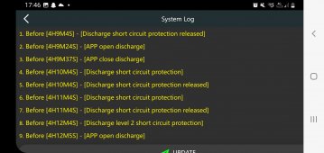
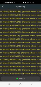
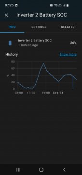
Sometimes this happening to my battery. Anyone know what could be the reason?
Battery size is 330a 52v
Battery size is 330a 52v


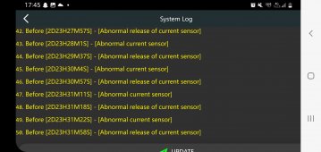
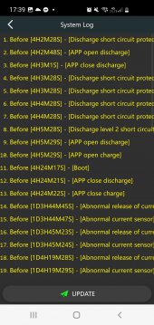
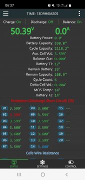
Forgot to tell. This never happens White discharging. Only while charging.Messages seem to indicate the BMS is passing too much load current.
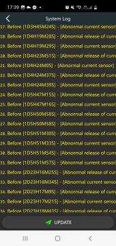
There are ten parallel chip resistors of 1 milliohm each that are for current shunt sensor reading. If one or more of these goes open for any reason the result is higher net shunt resistance with microcontroller ADC reading a higher voltage drop across shunt and calculating a higher current than actual.
Thougt this could handle 150a charge?Forgot to say that I have B1A20S15P
Charging is rated at continuous current while discharge is rated for maximum (short term) current.Thougt this could handle 150a charge?

I had a Momentary Brain Fart.
Battery Cells cannot be charged higher than 0.5C, so 100AH Cell can only take 50A MAX. THIS IS FOR LFP / LiFePO4
View attachment 113222
Cat seem to find your battery easily. It appears they use 37AH Cells to make 108AH Packs.
But this is li ion batteries. 30% of capachy is reccomended charge rate. 330a can be charged with 100a.I had a Momentary Brain Fart.
Battery Cells cannot be charged higher than 0.5C, so 100AH Cell can only take 50A MAX. THIS IS FOR LFP / LiFePO4
View attachment 113222
Cat seem to find your battery easily. It appears they use 37AH Cells to make 108AH Packs.


 diysolarforum.com
Thanks again. Yes i could try changing the settins. What are you renommending setting this to?A grid connected hybrid inverter is running in parallel with grid.
If there is a grid glitch, like a momentary dropout or voltage dip due to heavy grid load, like wind pushing tree branch into HV line, or lightning hit on grid, the inverter will go up to its overload surge limit before opening its pass-through relay connecting to grid.
This creates momentary high battery current.
BMS's have some delay on a max current overload to allow a short overcurrent but they also have an absolute 'short circuit' current level they will trip in a very short time to prevent BMS damage.
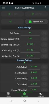
There are some BMS settings for how it handles max current surges that may help.
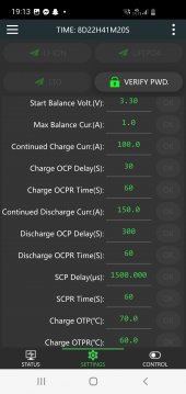
- max discharge current
- max discharge current trip delay
- short circuit protection trip delay
Actual short circuit current limit is firmware fixed and if it is too low, only way to avoid grid glitch shutdowns would be with max short circuit delay setting. That could be risky if you actually have a short circuit with a long recognition delay. Maybe that is the firmware bug talked about in other post. Grid glitches usually are less than 8 msecs. I think JK BMS defaults "SCP delay" user setting to 1.5 msecs.
Or should I try contacting jk bms and ask?Thanks again. Yes i could try changing the settins. What are you renommending setting this to?
I would try increasing the 1.5 msecs short circuit delay in 0.5 msecs increments until you don't have the issue anymore. I don't think I would go over 5 to 8 msecs in short circuit trip delay though.Thanks again. Yes i could try changing the settins. What are you renommending setting this to?