EDIT:
Problem still unsolved, but here is a TL;DR summary of the three thread pages we got so far:
my setup:
Lifepo4 8S EVE 280ah cells
JK BMS B2A8S20P-HC
Fchao 3000w 24v inverter
situation:
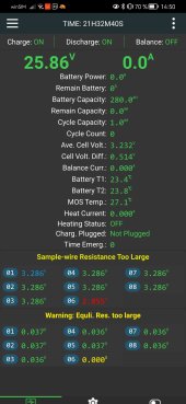
BMS installed, all readings in App are very good, no problems.
I tested the inverter for the first time for a few seconds with no problems, but I only tested for a few seconds.
2nd try a bit later the BMS shut down after a few seconds at 2000w.
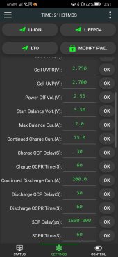
BMS shut down because it measured one cell to be below the shut off voltage.
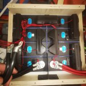
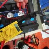
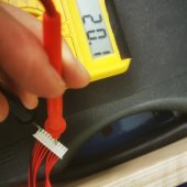
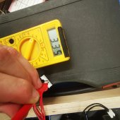
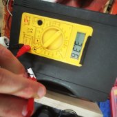
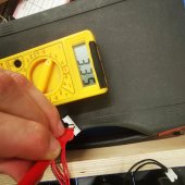
3 different Multimeters say that the cell is perfectly fine. <=1 mV deviation between cells. Measured directly on cells and also through the wiring harness, also tested with switched wires
conclusion: BMS is broken
But with new BMS and new wiring harness installed, problem still shows at the same cell.
Next step: load test
(I will keep this updated if I don't forget)
Hey guys, today I tested out my battery pack and im already having troubles with my bms ?
here's what happened:
my setup:
Lifepo4 8S EVE 280ah cells
JK BMS B2A8S20P-HC
Fchao 3000w 24v inverter
situation:
I tested the inverter for the first time with a 2000w load (heat gun). 1st try no problems, but I only tested for a few seconds.
2nd try a bit later the BMS shut down after a few seconds at 2000w. maybe something went wrong because I might have applied the load right away before the inverter was fully "powered up"?
Now there is no power on the P- side of the BMS.
The light on the BMS and on its start button is off. the light is on when the button is pressed, but there is no beeping sound and most importantly I can't connect my phone to see what's going on.
my testing so far:
I disconnected the BMS Balancing Leads and B- for a few seconds because I thought this might reset the bms.
I disconnected the BMS Balancing Leads again and measured the Voltage for every cell on the BMS . the balancing leads are wired correctly and no cell is drifting off too much.
3.32V/cell
26.6V total
I connected a charger (for the first time) and the BMS shortly turned on. I was able to connect via Bluetooth for a few seconds and looked at the system log. I think I read something about undervoltage protection before it shortly after shut down again and I wasn't able to turn it on/connect via Bluetooth again after.
I am not sure if I really saw an undervoltage fault, because it shut down while i was scanning over the log. Since my cells are at 3.3V it doesn't make any sense anyways, unless I mistyped the undervoltage protection parameter when setting up the BMS.
My last try would be to charge the battery again until it's completely full. My shunt and voltmeter say that my charger charges at 28.82V.
But when I measure the Voltage between the charger plus and the B- (not P- !) side of the BMS, my Voltmeter displays around 9V ?! Can someone explain that to me? Maybe my voltmeter is messing with me...
I haven't tried further charging yet, because im worried about something going wrong while charging with my old ass car/truck battery charger without the protection of the BMS.
thanks for reading all of this.
maybe someone can help me out? otherwise I might have to order a new BMS, because I have no idea what to do. I have very limited experience with solar installations and battery builds tbh. just learning by watching YouTube videos and reading forum post, like many people do I guess.
best regards
Felix
Last edited:


