diy solar

diy solar

Jk BMS shut down and unable to restart

Did you you pre charge with a resistor right before you connected the inverter?
I just watched this video by Will Prowse
Just like in the video I have a 24V battery and a 3000w Continuous/ 6000w peak Inverter, but I of course didn't precharge with a resistor like he strongly advised.
Seems like I have possibly made a big mistake. Do you think I have destroyed the BMS this way (and maybe even the inverter or anything else)?
I didn't have any sparks though, because I turned off the BMS discharge before connecting the inverter. but that probably doesn't make a difference, right?
 
wouldn't the continuity already have been confirmed by my previous test with the voltmeter?
View attachment 156309
serious question, I am honestly not sure
You are right, I did not look at your pictures correctly. It seems to be a BMS malfunction, I hope it is somewhere else. Unpluging and re-plugging does not make the problem go away? The pin terminals on the BMS side are all straight and not bent?

Sometimes the contact surfaces of the female terminal fails to make contact with the mating pin. See picture for reference only.
 

Attachments

  • Crimp.jpg
    Crimp.jpg
    161.5 KB · Views: 9
Last edited:
Switch the wires completely. (Both ends)
okay I might try that, thank you. unless the cause of my problem is indeed that I didn't precharge with a resistor like @Skypower suspected.
currently I am still not sure how big of a problem it is that I didn't know about that.

in case I should still give the wire switching a try, how would I do that on the plug side? can I just strongly pull on the wires and they will come out of the white plastic part of the plug without damaging the plug? currently it's getting quite late where I live so I can't take a closer look at the plug anymore today. I will check it out tomorrow though ?
 
You are right, I did not look at your pictures correctly. It seems to be a BMS malfunction, I hope it is somewhere else. Unpluging and re-plugging does not make the problem go away? The pin terminals on the BMS side are all straight and not bent?

Sometimes the contact surfaces of the female terminal fails to make contact with the mating pin. See picture for reference only.
okay thanks for taking a second look ? I did unplug and replug it a few times and the pins all look straight.
But I also suspect that there might be a bad contact between the female terminal and the mating pin. I'm not sure how to test it though ?
 
okay thanks for taking a second look ? I did unplug and replug it a few times and the pins all look straight.
But I also suspect that there might be a bad contact between the female terminal and the mating pin. I'm not sure how to test it though ?
I do only visual comparison beween a good terminal and a suspect one using a magnifier. You can use a small pin or the tip of an Xacto knife to carefully lift the locking flap on the housing so that you can pull the crimped terminal/wire out for examination.
 
I just watched this video by Will Prowse
Just like in the video I have a 24V battery and a 3000w Continuous/ 6000w peak Inverter, but I of course didn't precharge with a resistor like he strongly advised.
Seems like I have possibly made a big mistake. Do you think I have destroyed the BMS this way (and maybe even the inverter or anything else)?
I didn't have any sparks though, because I turned off the BMS discharge before connecting the inverter. but that probably doesn't make a difference, right?
Doubtful, that was the problem.
 
in case I should still give the wire switching a try, how would I do that on the plug side? can I just strongly pull on the wires and they will come out of the white plastic part of the plug without damaging the plug? currently it's getting quite late where I live so I can't take a closer look at the plug anymore today. I will check it out tomorrow though
Look at the plug and you will notice that part of the terminal has a tab that keeps it in place. Depress the tab, and the pin will easily come out.
The tab is on the end closest to the arrow. 20230707_163822.jpg
 
I do only visual comparison beween a good terminal and a suspect one using a magnifier. You can use a small pin or the tip of an Xacto knife to carefully lift the locking flap on the housing so that you can pull the crimped terminal/wire out for examination.
Look at the plug and you will notice that part of the terminal has a tab that keeps it in place. Depress the tab, and the pin will easily come out.
The tab is on the end closest to the arrow. View attachment 156319
thanks alot to both of you, I will definitely do that tomorrow ??
 
Quick update:

When I connected the charger my bms turned on again instantly. I went straight to the app to make some screenshots. When I was done with that I disconnected the charger again to first take look at the pics. Disconnecting the charger turned off the BMS.

It turned out the BMS shut down because it measured one cell to be below my power off voltage of 2.55V. I will attach a screenshot to show you the parameters I set.
But the measurement is not correct. I confirmed with 2 different voltmeters that the cell is, like all the other cells, at 3.35V.
(The BMS app says all cells are at 3.285V, except for #6 which was apparently below 2.55 V. After toroughly cleaning the contacts for balancing cable #6 again and reconnecting the BMS, the BMS turned on normally without the charger connected. On the flipside though it still measures incorrectly, and now displays around 2.85V for cell #6, so basically it still measures the cell to be empty and just barely above the power off voltage.

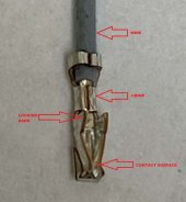
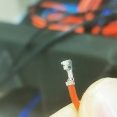
But as I said, I already measured the cell to be at 3.35V. I also, once again, measured the voltages on the plug side of the cable multiple times, to confirm that there is nothing wrong with the contacts or the wires. I will attach three pictures to show my measurements.
- I measured 20.1V between B- and cell #6
- I measured 3.35V or 3.36V between #5 & #6 and the same for #6 &#7 and "off camera" between all other cells as well to be safe

On the main page of the BMS app I got a warning saying "Warning: Equli. Res. too high" with 0.000 Ohm at cell #6.
Another warning says "Sample-wire resistance too large".

Am I correct in the assumption that my cells and the balancing cables and contacts are not the problem, but the problem is somewhere inside the BMS?
If so, I guess I have to get a new one, right? ?

Thanks for reading. If you have some ideas please share them with me ?
What is the total Battery Voltage you are getting (ground and plus on first and last battery)? The total reading on the BMS of 25.86 is the sum of the individual cells. Don't know if the BMS does the sum, or if it measures the difference between the ground and high voltage lead. BTW: do the readings on the connector, and not the battery terminal. that way you will know if the connection is bad. Also, do it step wise by keeping the black lead on the first battery, and make sure that each battery adds 3.xx volts. Reading the terminals on each battery doesn't tell you if you have bad connections.
 
This is a balance plug for a Neey balancer and it seems they use the same just with colors. I made this tool to remove or move the sockets as needed. I put 45 on the end and narrowed it a bit. It goes under the plastic edge push down gently while lightly tugging the selected wire. If you pushed down a bit too hard the tang will be too low but you can pry it up again with a partial insertion of a razor blade. IMG_0780.jpegIMG_0783.jpegIMG_0782.jpeg
 
What is the total Battery Voltage you are getting (ground and plus on first and last battery)? The total reading on the BMS of 25.86 is the sum of the individual cells. Don't know if the BMS does the sum, or if it measures the difference between the ground and high voltage lead. BTW: do the readings on the connector, and not the battery terminal. that way you will know if the connection is bad. Also, do it step wise by keeping the black lead on the first battery, and make sure that each battery adds 3.xx volts. Reading the terminals on each battery doesn't tell you if you have bad connections.
thanks, but I already did all of the above ? I measured twice with to different voltmeters on the connector (and also on the cells) and got 3.35V or 3.36V between each pin or cell and 26.8V total. Therefor I guess the BMS calculates the total voltage instead of measuring, which is why it shows 25.86V total
 
@tinyt @timselectric @Skypower i I managed to remove the pin the way you guys suggested ? it looks pretty normal to me. hard to say for sure though since both my magnifier and my camera zoom are crap ?
I just messaged the seller on aliexpress and hope they accept the refund. I will keep you updated
 

Attachments

  • IMG_20230708_142425.jpg
    IMG_20230708_142425.jpg
    348 KB · Views: 7
@tinyt @timselectric @Skypower i I managed to remove the pin the way you guys suggested ? it looks pretty normal to me. hard to say for sure though since both my magnifier and my camera zoom are crap ?
I just messaged the seller on aliexpress and hope they accept the refund. I will keep you updated
Pull another pin and the other end of the lead(eyelet). Swap positions at plug AND battery terminal. Verify cell lead position before connecting to bms. If conditions moved, you know it’s not the bms.
 
Pull another pin and the other end of the lead(eyelet). Swap positions at plug AND battery terminal. Verify cell lead position before connecting to bms. If conditions moved, you know it’s not the bms.
I know @timselectric already suggested that, but I was honestly to lazy to try it because I didn't have much hope. But you are right of course, I should make 100% sure. So i just tried it out and sadly the problem is still at #6, as you can see in the screenshot. Now we can be 100% sure the problem is in the BMS, right?IMG_20230708_190458.jpgIMG_20230708_190504.jpgScreenshot_20230708_190621_com.jktech.bms.jpg
 
Process of elimination can be timely, but it’s definitive. Looks to be sadly so.
 
alright, thanks so much to all of you ?? now I am only left wondering how the problem occurred. but if it's "just" a manufacturing mistake and therefor pretty surely won't accur again with the next BMS I'm happy ?
 
alright, thanks so much to all of you ?? now I am only left wondering how the problem occurred. but if it's "just" a manufacturing mistake and therefor pretty surely won't accur again with the next BMS I'm happy ?
If you don't have to return for replacement (if they will replace), and you are up to it, you now can open it up and do some troubleshooting. Hopefully it is just some cold solder joint at the pin #6 circuit.
 
If you don't have to return for replacement (if they will replace), and you are up to it, you now can open it up and do some troubleshooting. Hopefully it is just some cold solder joint at the pin #6 circuit.
if that's the case I will definitely take a look inside ?
 
Back
Top