timselectric
If I can do it, you can do it.
- Joined
- Feb 5, 2022
- Messages
- 18,637
Maybe the BMS wire crimp is loose.


Sounds like it was a connection issue.
I never liked rigid bus bars even the ones with bends in the middle, I think they are still rigid. I also don't like compression, in my assembly I put 0.08" thick rubberized sheets in between the cells and also side plates. The threaded rods are just to keep them together.Hi DIYrich, I thought I could just try out your suggestion since I would have to disassemble the compression box for my cells anyways if I have to replace the cell. I switched cell #6 with #7.
Surprisingly the problem did not follow the cell, in fact, it somehow disappeared ??!
one difference in the test setup right now is that the cells aren't compressed anymore. mine could have been too compressed, I have no idea if I am near the recommended 300kg. can too much compression cause problems that simply go away once the compression is gone?
But how, I don't see how it wouldn't have been solved by previous testing. all bms connections were renewed, the one at cell #6 was tested so many times. and if it was a connection issue, then why wasn't it there from the beginning? ?Sounds like it was a connection issue.
Loose crimp will be an intermittent connection integrity. Pull gently on the wire and see if it moves in and out.But how, I don't see how it wouldn't have been solved by previous testing. all bms connections were renewed, the one at cell #6 was tested so many times. and if it was a connection issue, then why wasn't it there from the beginning? ?
wow that's a really clean setup ?I never liked rigid bus bars even the ones with bends in the middle, I think they are still rigid. I also don't like compression, in my assembly I put 0.08" thick rubberized sheets in between the cells and also side plates. The threaded rods are just to keep them together.


You are right of course but in my case that would mean that I somehow managed to badly crimp the wire for only cell number 6 twice, even though I used expensive crimps, high quality pliers and checked each crimp before the installation ?Loose crimp will be an intermittent connection integrity. Pull gently on the wire and see if it moves in and out.
Your setup is nicer.I also mainly compressed the cells for stability. I put a sheet of packaging foam in the box and pressed it together against the cell walls with one of the side boards that make up the wooden box. Compressing the foam took a bit more force than I thought, but I would say it's probably still below the combines 600kg for two cell walls. hard to say for sure though, obviously screws can quickly build up alot of force with little effort.
Between each cell there's a 1mm rubbery sealing plate (Tenasil NG) to prevent a short between the cells.
After compression I installed the bus bars, they are pretty flexible but obviously no where as much as the cables you used.
But in general I think my setup should still be on the safer side, compared to all the ones with rigid busbars and a metric ton of compression ?

thank you@fx99
Your setup is nicer.
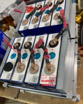
This is just my guess. It seems that the terminals of the cells are made of 3 separate pieces, the bolts, the flange (B in the picture) and a round stud (A in the picture).
If the BMS again reports an anomaly, use your DMM and measure if there is a voltage drop between A and B and C of the suspect cell. It is possible that there is a manufacturing fault between A and B that appears intermittently.
View attachment 157972
")
I knew it ?Ghost gremlin lol

I doubt there’s a problem with post to mount weld. I’ve seen the result of a drop test.@fx99
Your setup is nicer.
This is just my guess. It seems that the terminals of the cells are made of 3 separate pieces, the bolts, the flange (B in the picture) and a round stud (A in the picture).
If the BMS again reports an anomaly, use your DMM and measure if there is a voltage drop between A and B and C of the suspect cell. It is possible that there is a manufacturing fault between A and B that appears intermittently. This is assuming that A and B are separate pieces, the picture is not very clear.
View attachment 157972

damn that sounds excessive but you are probably right. won't have to worry about that again ?I remove the heat shrink and expose the barrel. I fold the wire so the bend just comes through and crimp with an MC4 crimper that the jaw’s small position has been oriented for maximum force close to the hinge. Then a quick wetting of 40/60 solder just to plug the spot where the wire bend is because the new shrink tube can’t quite seal that spot.
When problems go away and I’m not sure why, just gets me more concerned. Can It happen again?damn that sounds excessive but you are probably right. won't have to worry about that again ?
but was that general advice or do you also think my crimps are the problem? I'm so sure that they are good after all the testing ?
wow that's insane. good to know that I probably won't have to worry about them ?The post inside the cell is actually what bent. Yes the internal resistance and voltage was exactly the same as other cells. View attachment 157988
I did buff them and clean them with Isopropanol. Used antioxidant ("Wago Alu-Plus", basically the same as Noalox) as well ?I highly recommend a quick buff with 3M cloth on the mount surface and the bottom of the flexible buss bars. Use antioxidant on the contact surfaces.
good thought, but I would have noticed that during cleaning for sureJust a thought. On the flexible buss, could they have forgotten to remove a protective film or something from the manufacturing process?
yeah I'm not happy with the situation either ?When problems go away and I’m not sure why, just gets me more concerned. Can It happen again?