diy solar

diy solar

Jk BMS shut down and unable to restart

Hey guys, it's time for the update:
the new BMS has arrived ... and now I'm even more confused than ever before ?

The BMS arrived today and I tried it out straight away, eager to finally get the project done. But when I connected it, the app still showed me the same undervoltage alarm, at the same cell even. I checked all the wires again, this time with a very accurate multimeter, and, measuring through the balancing leads, the voltage was pretty much exactly the same (±0,001V).
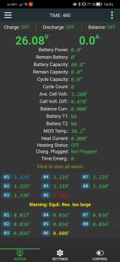
But the BMS App showed the Equi. Res. Alarm for cell #6 and measured it's voltage at roughly somewhere between 2.25V to 2.4V. The voltage it measured jumped around alot.

Although we already concluded last time that the balancing leads were okay, after switching them around on the plug and the cells, I tried out the new leads that were delivered with the new BMS.
Before I have tested it with the old ones, since I of course thought they were all good. (I still had them because the seller said it's okay if I keep the old balance leads, but I had to send back the BMS.)
So after about an hour of installing the new cables and making really sure everything is clean again, I tried again but to no avail.

The only difference was, that it now measures the voltage for cell #6 at around 2.7V to 2.8V (still jumping around)
Therefor I would normalls assume that there is indeed a bad contact at #6 somehow, but why would all my multimeters measure the cell correctly then? Is there perhaps a difference in how the BMS measures the voltage compared the to a multimeter?

I really have no idea what to try now, since I though buying a new BMS was already my last option and I was sure it would be successful ?
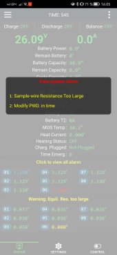
Screenshot_20230714_160503_com.jktech.bms.jpgScreenshot_20230714_160458_com.jktech.bms.jpg
 
Maybe something wrong with cell #6 which does not show when using the high impedance DMM measurement. With the BMS disconnected, can you put a DC load across the DMM test leads and re-do cell voltage measurements?
 
Maybe something wrong with cell #6 which does not show when using the high impedance DMM measurement. With the BMS disconnected, can you put a DC load across the DMM test leads and re-do cell voltage measurements?
hey tinyt, thanks for answering so quickly ✌️ I would try of course, but I don't quite understand yet. What kind of DC load do you mean?
 
hey tinyt, thanks for answering so quickly ✌️ I would try of course, but I don't quite understand yet. What kind of DC load do you mean?
Car incandescent tail light, resistor maybe 5 ohms (3.2V / 5 = 0.64A) or slightly higher, etc. Compare DVM reading of cell #6 with readings of other cells. Readings should be close to each other if all have internal resistance and charge capacity close to each other.
 
I'm at a loss for the next step. With what you are seeing, I would swear that it was a bad connection on the balance wire.
 
I'm at a loss for the next step. With what you are seeing, I would swear that it was a bad connection on the balance wire.
sucks to hear that, but thanks so much for helping me so far :)
now I can only hope that someone even more experienced than you can help, because I am absolutely at loss here ?
maybe @tinyt is onto something with his last posts, but I will have to do that tomorrow since it's getting quite late here across the big pond ??
 
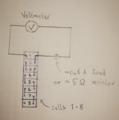
View attachment 157454
do you mean like that? ? for each cell of course
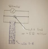
The load should be in parallel with the two DMM probes, not in series. This way each cell being measured is loaded by the resistor.
If the resistor is 5 ohms, it should be (3.2 x 3.2)/5 = 2 watts or higher. Make sure you measure only one cell at a time.Redraw.jpg
 
Last edited:
The load should be in parallel with the two DMM probes, not in series. This way each cell being measured is loaded by the resistor.
If the resistor is 5 ohms, it should be (3.2 x 3.2)/5 = 2 watts or higher. Make sure you measure only one cell at a time.View attachment 157484
thanks for the correction ? all I could find so far though was a 25W 33 Ohm resistor that I wanted to use for precharging and a 2W led lamp, but it's meant for 230V AC ? couldn't get any different results with those, but that's probably to be expected.
Maybe I will find something more fitting somewhere, otherwise I could just order a resistor.
But I was wondering if the resistor would even do anything in the parallel circuit you drew, because I thought all the electrons would take the path of least resistance through the Multimeter. edit: nevermind, the Multimeter has way higher resistance of course
Can you help me understand this a bit better? Or is there a specific term for this kind of measuring procedure that I can look up to inform myself better instead of getting on your nerves by possible asking quite stupid questions? ??
 
Last edited:
Can you help me understand this a bit better? Or is there a specific term for this kind of measuring procedure that I can look up to inform myself better instead of getting on your nerves by possible asking quite stupid questions? ??
It is similar to load testing a car battery (plenty of youtube info).
You apparently have ruled out the BMS. You also have checked sensor wire connections for possible high resistance.
I assume also that you have swapped out the sensor connections to cell #6. and in doing this you also have re-tightened the bus bars.
Assuming all connections are correct and tight with no high resistance, the only thing I can think of is cell #6, hence my suggestion of load testing it.
 
thanks for the correction ? all I could find so far though was a 25W 33 Ohm resistor that I wanted to use for recharging and a 2W led lamp, but it's meant for 230V AC ? couldn't get any different results with those, but that's probably to be expected.
Maybe I will find something more fitting somewhere, otherwise I could just order a resistor.
??
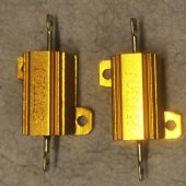
A 1 ohm 10 watts or higher will be better but you will need heavier guage test connections to this resistor, also the resistor will get hot the longer it is connected. Temperature rise of the resistor is an indication of proper test setup and that the cell is delivering about 3 amperes.

I have used this to check the condition of used LIFEPO4 cells that I purchased way back.
 
Thanks guys, I think will have to buy another resistor then for the test. Will take a few days then for it to arrive but I couldn't find any low voltage loads. I was wondering if it's also possible to put a 24v load across the whole battery while measuring the individual cells. Or maybe connect one of the bigger resistors I have laying around (33 Ohm, 25W) like that between B- & B+. Would that work or should I go ahead and order a smaller resistor?

@tinyt You mean 1ohm is better because lower resistance --> higher load --> more accurate measurements right? ?

IMG_20230716_195143.jpg
 
I was wondering if it's also possible to put a 24v load across the whole battery while measuring the individual cells. Or maybe connect one of the bigger resistors I have laying around (33 Ohm, 25W) like that between B- & B+.
Good idea. maybe no need to buy a low value resistor.

Also, have you top balanced the cells?
 
nice, than I will try that first ?

the cells I bought were already top balanced. I wanted to be sure to have really good cells, so I bought A+ cells from a company here in Germany (lifepo.de) that checks all the cells that they get from China and initializes them for you.
„The cells are loaded, balanced and fully initialized before shipping.
Each cell has been individually tested and approved by the manufacturer EVE
Each cell was checked several times during the production process:
capacity check
triple voltage test with open circuit voltage
triple internal resistance test
Cells matched by internal resistance and capacity“

At least that gives me some hope that I may be able to get a refund if we can prove that the cell is damaged ?
 
TLDR, did you try moving cell #6 to cell #1 position? Does the problem follow the cell? Or is the problem always cell position #6 regardless of which battery is there? If you have a different wire harness, that eliminates the harness as the problem.

When using the bank under load, does the BMS, inverter and multi meter show the same voltage for the bank?
hi, I'm very sure that the problem would follow the cell, so I haven't tested it specifically. Firstly I switched the wires around on the BMS and the cells, then got a new BMS and also new wire harness now. still shows the problem at the same cell.

I haven't put the bank under load through the inverter since the BMS problems started so I can't say. Not sure about trying it now either, seems sketchy if the cell is actually damaged and I don't know if the BMS would allow it either during an alarm.
Maybe you have read the last few messages, but to conclude I will do a load test soon without the BMS connected, only a resistor between B- and B+, and then measure each cell again
 
Good idea. maybe no need to buy a low value resistor.

Also, have you top balanced the cells?
I tried it out with the 33ohm resistor across all cells.
I checked with the multimeter and, like expected (26.7V : 33 Ohm), measured a 0.8A load.
that may not have been enough though, because there wasn't any difference in the cell voltages. With or without this load the cells all measured 3.340-3.341V.
 
TLDR, did you try moving cell #6 to cell #1 position? Does the problem follow the cell? Or is the problem always cell position #6 regardless of which battery is there?
Hi DIYrich, I thought I could just try out your suggestion since I would have to disassemble the compression box for my cells anyways if I have to replace the cell. I switched cell #6 with #7.
Surprisingly the problem did not follow the cell, in fact, it somehow disappeared ??!
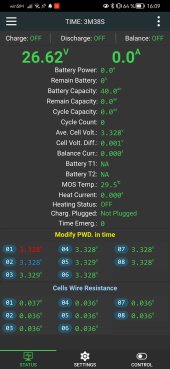
Screenshot_20230717_160910_com.jktech.bms.jpg
I only have the BMS on for maybe 15min now since I'm writing this update right after taking the screenshot above, but so far no warnings.
But of course I am very sceptical of everything magically being good all of the sudden:
- I have redone the connections so many times before already and each time I gave more care to cleaning and proper tightening then now.
- The BMS measures different cell voltages than my Multimeters (BMS: 3.328 vs Multimeter 3.341)
-when I installed the first BMS for the first time it only showed a warning a few days later when I used the inverter for the second time

one difference in the test setup right now is that the cells aren't compressed anymore. mine could have been too compressed, I have no idea if I am near the recommended 300kg. can too much compression cause problems that simply go away once the compression is gone?

of course I will do some testing with the inverter later or tomorrow maybe, but for now I am.very curious what you guys think about this new situation. are you as confused as I am? ?
 
Back
Top