diy solar

diy solar

Layout Check

THUDGUN

New Member
Joined
Jun 6, 2022
Messages
43
Been going back and fourth on how I want my system to work. Here's the layout I'm thinking on, but I need a sanity check, to make sure there are no obvious issued, then I can start creating more detailed plans.

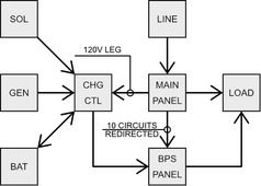
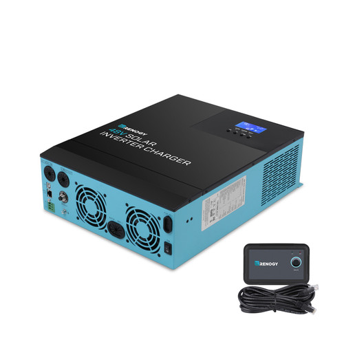
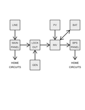
Thinking of pulling a 120V line, with a 30a breaker, from the Main Panel to my Renogy 48 volt, 3500W Inverter Charger.

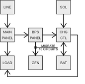
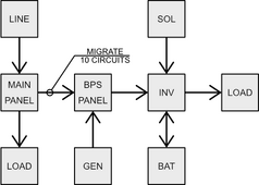
Then redirect 10 circuits from the Main Panel, to the Bypass Panel.
It occurred to me I don't really need a bypass panel, I think I could have just used a regular, auxiliary panel in this configuration, but it's what I have.

This is the simplest way I could figure out how to integrate everything into my home. Anyway, are there any obvious problems, and what should I be on the lookout for, moving forward, assuming this would work?

Thankyou kindly.
 

Attachments

  • Power Layout.png
    Power Layout.png
    18.5 KB · Views: 14
I've never seen a charge controller with PV and generator inputs.

For the most part, I don't understand any of your drawing.
 
I've never seen a charge controller with PV and generator inputs.

For the most part, I don't understand any of your drawing.
That was one of the reasons I got it, that and it was on sale, at the time.
In the drawing, the PV, Generator and Batteries are all plugged into the charge controller. Line power is taken from the main panel, to the charge converter.
10 circuits are migrated from the main panel to a bypass electrical panel. This will be everything in the house I want to run off solar/battery. The load side of things don't change.
 
Got a link? It still sounds like nonsense
Page 5 of the owners manual says Power (utility) or Generator. There aren't two discreet connections for them, but either can be used. I'll be hooking it up through a switch, so both can't be connected at the same time.
 
Last edited:
Maybe this is better?
 

Attachments

  • Power Layout_02.png
    Power Layout_02.png
    13.7 KB · Views: 7
Inverter Charger, right. What's the technical definition of a Charge Controller?
 
Inverter Charger, right. What's the technical definition of a Charge Controller?
Umm, PV to DC to charge a battery. Some also have a DC "load" output for small DC loads, like a light or relay.
I don't have a good "definition"
One huge difference is that a change controller doesn't touch AC voltage.

Does this inverter include and internal transfer relays/switch? If so, normal connection would have the inverter between the main and backup/critical loads panel.
If not, you likely need some way to lock out the grid connection when running the inverter/generator to protect lineman working to fix an outage.

I think the arrow on your "gen" is backwards. The generator connection would be better done either through an inverter with dedicated generator input or a manual transfer switch.
Ah, I assumed a charge controller was just a system that automatically controlled the different states of charge. What's the upper voltage, lower voltage, rate of charge and discharge, what's the hierarchy of source power, (solar/batter/line/etc.) and such. Is Solar Inverter Charger appropriate, or is All-In-One more accurate?

Yes, that arrow is backwards... Don't know why I didn't notice. It's in the middle of the diagram...

The Bypass Panel has an input for the generator built in. The entire panel is manually switched between line and generator (bypass), so they can never be connected at the same time. The 10 circuits, which will be migrated to the bypass panel, will no longer have any connection to the main panel, except for the earth ground, I believe. (I will have to confirm how ground gets to the earth. I believe there is only one in my house.) The only way these circuits will receive power is through the inverter charger, so there should be no chance of back-feed into the grid. These circuits should be completely isolated.

I'm comfortable around electricity, but I do plan on having a licensed electrician check my work before I throw the switch, and assuming no one sees any real issues with my theoretical layout here, I will then draw out more detailed plans, so I am sure to use the correct wiring, fuses, etc. I already have a bank of batteries, but haven't built the enclosure. I have built the enclosure for the All-In-On, which has it's own breaker box, a pre-load switch, for the battery bank, temperature sensors, etc. Haven't bought solar panels yet. That will be the last part of the system to get integrated. Just want to be sure I can add it, as simply and cleanly as possible. I don't want to have to go into my walls again, if I can help it.

I really appreciate your time, in looking over my fumblings. I don't want to screw this up.
 
Is Solar Inverter Charger appropriate,
Not a thing
or is All-In-One more accurate?
Probably, or just inverter.
Yes, that arrow is backwards... Don't know why I didn't notice. It's in the middle of the diagram...

The Bypass Panel has an input for the generator built in. The entire panel is manually switched between line and generator (bypass), so they can never be connected at the same time. The 10 circuits, which will be migrated to the bypass panel, will no longer have any connection to the main panel, except for the earth ground, I believe. (I will have to confirm how ground gets to the earth. I believe there is only one in my house.)
Good info on the bypass panel. Ground and neutral are probably passed straight through everywhere and connected back to the main panel as is.
The only way these circuits will receive power is through the inverter charger, so there should be no chance of back-feed into the grid. These circuits should be completely isolated.
Maybe I'm reading the diagram wrong, but it looks like you've got the inverter output hooked up the your main panel not the critical loads panel. This is my biggest concern.
 
Not a thing

Probably, or just inverter.

Good info on the bypass panel. Ground and neutral are probably passed straight through everywhere and connected back to the main panel as is.

Maybe I'm reading the diagram wrong, but it looks like you've got the inverter output hooked up the your main panel not the critical loads panel. This is my biggest concern.
Those migrated circuits are supposed to be from the main panel to the bypass panel.
'Load' here, is just meant to be 'parts of the house'. Since those will now be separate circuits, I guess it should look more like this?
 

Attachments

  • Power Layout.png
    Power Layout.png
    18.4 KB · Views: 1
So you've got circuits in the main panel, 10 in the critical loads panel (relocated from the main)

What's in the "load" box all the way on the right? This should be inverter output connection, right? I'd expect that to connect to the critical loads panel.
 
So you've got circuits in the main panel, 10 in the critical loads panel (relocated from the main)

What's in the "load" box all the way on the right? This should be inverter output connection, right? I'd expect that to connect to the critical loads panel.
Crud. This won't work. The Inverter has to come before the bypass panel. The bypass panel holds the 10 circuit breakers that lead to what I want to have power. Bypass panel will be the critical load panel, which then goes to the individual circuits, migrated from the main panel....
I guess I could ignore the bypass note. They'll be moved, and so it's just confusing the diagram.

So, Generator and power from the Main Panel will come into a Lockout Panel.

Does this make more sense?
 

Attachments

  • Power Layout_02.png
    Power Layout_02.png
    13.5 KB · Views: 2
Yeah, that looks pretty good to me.
Does your inverter sell back out the input?
Back to the grid? I don't believe so, but it's not something I'm interested in, either way. The intent is to have a backup system, not lower my power bill. If I can cut utility usage. That, and it's a fun experiment.


My next step will be to diagram each part of the system, so I know what I still need to get, and also ensure it will be a safe, and effective system. Is there anything in particular I should be keeping an eye on, and make doubly sure I understand what I'm doing and avoid problems down the road?
 
My concern there was the inverter attempting to sell back to the generator and causing issues. If it doesn't sell, you should be fine.

I'm just surprised someone who knows that inverter better hasn't jumped in. Renogy doesn't have a great reputation here, after all they don't make their own inverters just get their decals installed on someone
Yea, had I known that when I got this one, I would have gone a different route, but here I am. If this works well enough, I'll save up and replace it. Just keep it to experiment. Trying to make each section of the system modular enough that I can upgrade, more easily...

Thanks for all your help.
 
Back
Top