diy solar

diy solar

Length of sense wires

hwse

Solar Enthusiast
Joined
Jan 2, 2021
Messages
585
Is there any reason to leave the sense wires on the BMS at the full length on the wiring harness or can they be cut to length as needed to reach each cell?
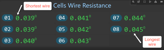
My JK BMS should be here tomorrow, and I would like to cut them to length to keep the build tidy. I believe that the JK actually auto calculates the resistance of the sense wires so it should not matter.
What say you?
 
My BMS is mounted on one end of the build with is a 2p4s so it is almost 2-ft long. I was hoping to trim each to length which would make the shortest wire about 18" shorter than the longest.
I believe that on other BMS's the sense wires need to be the same length but that the JK BMS will calculate the resistance of the wires when it does its active balance thing and inter that actual value into the unit to compensate.
Can anyone familiar with the JK BMS verify this or provide the actual way that the sense wire resistance it figured on the JK?
The screen shot Is of a JK app printout that I pulled from the forum. This user told me that the wires had been cut to length.
 

Attachments

  • jk resistance.png
    jk resistance.png
    146.8 KB · Views: 3
answer here.
 
Most BMS's do a capacitor storage sample and hold multiplexing transfer to bring the cell voltage representation on the sampling capacitor down to the base voltage the microcontroller internal ADC works at. The small value capacitor cell voltage sampling charge current through the sense wire is minorly effected by sense wire resistance. This is usually insignificant compared to variance caused by random inverter load or charge currents induced voltage drop through bus bars and battery terminal connections.

Do not run sense wires in close parallel proximity to battery cables as the coupling induced inverter random currents can corrupt the cell voltage readings.

All BMS's momentarily shut down balancing current to make the cell voltage measurements, periodically, to prevent sense wire resistance and balance current from corrupting cell voltage readings.

It is better to have the BMS sense wire neat and orderly then having a rat's nest of sense wires.
 
Last edited:
Most BMS's do a capacitor storage sample and hold multiplexing transfer to bring the cell voltage representation on the sampling capacitor down to the base voltage the microcontroller internal ADC works at. The small value capacitor cell voltage sampling charge current through the sense wire is minorly effected by sense wire resistance. This is usually insignificant compared to variance caused by random inverter load or charge currents induced voltage drop through bus bars and battery terminal connections.

Do not run sense wires in close parallel proximity to battery cables as the coupling induced inverter random currents can corrupt the cell voltage readings.

All BMS's momentarily shut down balancing current to make the cell voltage measurements, periodically, to prevent sense wire resistance and balance current from corrupting cell voltage readings.

It is better to have the BMS sense wire neat and orderly then having a rat's nest of sense wires.
Avoiding the rat's nest is why I would like to cut the sense wires to length. given that the distance to the cells varies by about 18" from longest to shortest, I either cut them to length or will need to have coils of wire to take up the extra length. It seems to me that coils of varying numbers of turns would produce more problems than the difference in resistance through the wire. This would be especially true if the BMS is actually measuring the resistance for itself to compensate for the difference.
With the 2A active balance current in the JK BMS I suspect that they do this step differently than the BMS's with tiny passive balance currents.
Here is a drawing of how I will run the sense wires.
 

Attachments

  • sense wires.png
    sense wires.png
    226.4 KB · Views: 23
You can trim the wires down in length.

The JK measuring of wire resistance involve checking battery voltages with and without balancing current. It is checked to ensure there is not too much series resistance to affect the operation of the buck DC-DC converter used to charge the supercaps.

It also has to check to be very sure balancing leads are connected properly. Running the buck converter with more than one cell input voltage could overvoltage the supercaps and destroy them.

The supercaps are in parallel so charge storage must be lower voltage than cells and current pushed to any lower SOC voltage cells during balancing are fed through a boost DC-DC converter fed from the charged supercaps. A buck switcher with passive damper diode is not very efficient at this low voltage.

All the 8 pin SOIC's near the sense leads connector are the MOSFET mux switching array for balancing connections to select the 'to' and 'from' cell pair for the active balancing.

JK Super cap charger Buck DC-DC conveter copy.jpg
 
Last edited:
Thanks for the great explanation. based on the display on the app and how the resistance changes in a rational fashion when the wires are trimmed that seemed to be the case but then there is the "conventional wisdom"... Which leads to so many strident proclamations. Will my proposed layout of the sense wires that run down the center of the cells eliminate the problem with close parallel proximity?
 
If you keep balancing leads that run in parallel to battery cables 3 to 5 inches away it should be sufficient to avoid magnetic coupling from large ripple current in battery cables.

Folks think battery cables are just 'DC current'. A sinewave inverter at moderate to high power produces a large time varying current on battery lines. The current is an offset sinewave at twice the AC line frequency. The peak-to-peak value of this sinewave current can be up to 2x the average DC current as read by battery monitor. This creates a strong time varying magnetic field around the battery cables that can inductively couple to parallel adjacent wiring. It can cause buzzing in any loose-fitting ferromagnetic metals like a door cover on a steel DC breaker box.

Taping positive and negative battery lines together helps to cancel their magnetic fields. It also reduces battery cables series inductance that will reduce voltage ringing on inverter DC input that can be damaging to inverter.

To really freak you out, a low freq inverter with a poor power factor AC motor load can actually have a reverse instantaneous current flow on battery cables for a portion of the AC cycle. Poor AC power factor loads also create higher peak current from batteries.
 
Last edited:
If you keep balancing leads that run in parallel to battery cables 3 to 5 inches away it should be sufficient to avoid magnetic coupling from large ripple current in battery cables.

...
Does the routing of the sense wires on my drawing in post #6 do what you describe? At this time, I do not have a large invertor but am planning to add the Samlex EVO 1212f HW and I had seen the note in their installation manual about taping the + & - together.
I am not sure if the EVO is high or low freq but it appears to have a very good charging capability for LFP batteries.
 
Back
Top