diy solar

diy solar

LiFePO4 heating pad for cold temperatures

Just remember that these cells have an optimal storage temperature too and exceeding it can hurt as much as being too low.
Yeah, the spec sheet for these cells (EVE 230Ah) only shows that the charge and discharge range goes up to 45°C (113°F), and they show a curve that shows the cycle life is longer at 25°C (77°F) than it is if continually charged / discharged at 45°C (cycle life at 45°C is about half of that at 25°C). EVE seems to use 25°C as their temp for their test conditions, and I've read elsewhere that 25°C is considered by the manufacturers to be the sweet spot.

Just FYI, the EVE 280 "N" cells show a charging and discharging range up to 60°C, which is 140°F, and the "K" version shows it up to 55°C (131°F).

The probe that I call "bottom of cells" is actually on the aluminum plate, between two rows of cells. So I think cutting off the heat when the plate gets to 90°F should still be fine. Fact is, my testing may show that the bottom plate never gets to 90°F, even when the outside temp is in the 20's.

I should have mentioned: I'm only using two 12W 12V silicone heating pads right now, wired in series to be driven by my 8S 24V pack. I do have two more of these pads, so after my winter testing I can decide if 24W of heat is enough or if I want to up it to 48W.
 
Well. Operating temp extremes are one thing but storage and operation should be as close to a nominal center point for each as possible as I understand it.
 
  • Like
Reactions: Dzl
Well. Operating temp extremes are one thing but storage and operation should be as close to a nominal center point for each as possible as I understand it.

Ummm... Ok. Not sure what to do with that. I guess the "nominal center point" for these cells would be the halfway point between 0°C and 45°C, which is 22.5°C (72.5°F). Is that what you mean?

My SCC will be on and engaged all winter. There may be snow on the panels a few days, but most days the SCC will be sitting at float, giving the system power to keep the temperature up.

I'm shooting for between 50°F and 60°F over the winter. Like I said, the manufacturer seems to say 25°C which is 77°F. I don't think Eve would tell me I'd be much better using 60°F to 70°F as a range. Since most of the time that I'm engaging the heater will be when the heater is literally the only load on the battery, I don't see any point go going higher.
 
Well. Operating temp extremes are one thing but storage and operation should be as close to a nominal center point for each as possible as I understand it.
That is my thought. Why not keep the batteries at a nominal temp.

I can see temps down to -40 and I'm trying out a seedling heating pad in an insulated box.
Recently the night temps have fallen to 28 F and the box is keeping relatively steady at 58 F

Actual temp reading of each battery varies about 4 degree F on the warm (inside probe) to the outer side probe
(two temp probes on each BMS)

I placed the pad on edge between two 8s battery packs. (400Ah)
The tubing covering the compressor rods holds the pad away from the cells.
My battery bank can afford the 22w load of the heating pad even if it runs 24/7
 
I have no intention of keeping my cells all roasty warm 75 degrees all winter. On at 40, off 45. They will have to shiver a bit.
Yeah, I think that is fine. I probably want to stay above 40°F, just because at that temperature I believe I've seen that the charge rate has to be throttled back a bit. With no loads other than the heater, I don't expect any heavy charging, but....

I'm hopeful that my insulated box and 50°F-60°F range will take very little energy.
 
A sensible approach. I see no reasonable objection to that.
The main concern is not to charge below freezing.
Agreed, but arguably equally important is not to charge at high C-rates just above freezing (~0-5*C range), but since most of us don't/and realistically can't charge at high C anyways, its not such a huge concern for most solar applications, but still a consideration.

The manufacturer datasheets that I've dug up that give detailed data, suggest that above freezing but below 5*C or 7*C charging should not exceed ~0.1C (some manufacturers say <0.2C). 5C = 41F, 7C = 45F
 
Dang that tape is kind of cool. I just upgraded my heat setup using a 3d printer silicone heat pad + aluminum 1/4" plate as a raised floor (minutes ago)-initial test in progress. Turns out there isn't a lot to be had in the USA &/ ETA < 6wks in the 12v flavor and with acceptable wattage/size. I ended up with a 120w 12v 120x120mm w/ thermistor.

The previous setup was an incubator heater (12v 100w and 60mm fan, measured high 92w @ 13.34v on Victron BMV) and never got used in the wild. Not that it didn't work - it passed all tests (sitting on my patio in 20*F) - but fan crapping out was a concern and I wanted to control both the fan and its heating element separately. Even got PID control working on the heating element but I disliked the thought of fan failure, relay sticking on, more wires in an increasingly cramped enclosure, yadaya.

View attachment 1662

Anyway, on to the new...

A microcontroller paired with a 3d printer heat bed module MOSFET operates the heat pad at the perfect temperature (as measured by the incorporated thermistor) so the floor will never really deviate from the setting. Once it's up to temperature it only requires a trickle of wattage to maintain in open air tests (maintain 120*F in 66*F ambient, still air..) , so I'm hoping this will be a tiny amount of draw once I throw it in the truck and the box it'll reside in is all sealed up, just trying to maintain like 47*F

Heat pad $16 (or pick anything with better dimensions for your build, or a full wrap, or something from the slow boat)
Some serious aluminum $27
A 3.3v suitable initial switching MOSFET module $9
One of the two of this 2pk of 3d printer heat bed modules, so $5.50
A $5 arduino nano clone, or a $19 particle photon, or a ESP8266/esp32 dev module for $8, whatever
Some jumper wires from a many-hundred pack
A breadboard

View attachment 1663

This is a 12 watt heater without incorporated thermistor. I ended up ordering two of these, advertised as bee colony warmers or something. Could have made them work but weren't adhesive backed and were less durable than the one in the parts list that I ultimately used. These seem like the standard fare silicone heaters that you'd get from China, and they heated well. Shoo, I might have been able to get by with a single 12w pad... but I wanted to be sure, and I liked the durability and 3m backing of *

View attachment 1664

View attachment 1665

^ the aluminum doesn't really have a hot spot even operating the pad at 90w. Maiden test capped at 50w. But still, added a strip of silicone from a cheap 3pk of silicone baking sheets from amazon. It's nice and nonskid, thin, transfers heat well, felt like the right thing to do after drinking a lot of beer and looking in to a stupid box for 3 hours with my hands on my hips like a dingaling.

View attachment 1666

^the same cell holding strategy as in the initial incubator fan heater. You can see why this wasn't really a great solution when the heat was blasting from the opposite side of the can, hitting a wooden wall, trying to maintain a hunk of cells.

View attachment 1667

loaded... more insulation has been shoved around certain places, cells have been locked in place from movement in any direction, ceiling on top of the whole shebang with BMS and other crap mounted on it...

View attachment 1668

I'm going over the top with this project but for simple insanely consistent heating... give DIY control some thought. Plug some wires in to numbered holes, connect some positive and negative wires to screw terminals, copy paste 20 lines of code and press play. Aluminum is biggest expense. My hope is that this heats slowly from the bottom so I don't get the BMS or Victron BMV prematurely enabling charge because... heat rises and stuff.

Edit: it's been like 2 hours running the plate at a maintained 78.5*F and is requiring about 8 watts to do this, installed, cells atop it. Starting temp was 67*F combined avg between BMS' onboard temperature reading and its separate probe. In that 2 hours time I've reached 71.6*F combined. This is not a fast heating solution so if I ever program it to shut off it'll be right after sundown, turning on many hours before sunrise. If I can leave it on permanently I'm just going to do that.. and I have a feeling I probably can. Low and slow works for me.

A mildly interesting observation is that it was taking like 0-4w to maintain 120*F in 66*F ambient, open air, plate just sitting on that wooden donut on my coffee table. That was reached in 2 minutes according to thermistor reading, and plate was warm-warm after a few additional minutes of soaking. Guessing the cells and all the materials are sucking heat off the plate which is requiring more to maintain
holy CARP that is BEAUTIFUL!!!!
 
Ummm... Ok. Not sure what to do with that. I guess the "nominal center point" for these cells would be the halfway point between 0°C and 45°C, which is 22.5°C (72.5°F). Is that what you mean?

My SCC will be on and engaged all winter. There may be snow on the panels a few days, but most days the SCC will be sitting at float, giving the system power to keep the temperature up.

I'm shooting for between 50°F and 60°F over the winter. Like I said, the manufacturer seems to say 25°C which is 77°F. I don't think Eve would tell me I'd be much better using 60°F to 70°F as a range. Since most of the time that I'm engaging the heater will be when the heater is literally the only load on the battery, I don't see any point go going higher.
Well. That's what I mean. Nominal being the ideal range, center of being self explanatory.

I don't recall what those values are off the top of my head but I do know that the ideal temp range is smaller than the working range is all.

I swear there was a test paper around I had read that covered either a decrease in capacity or longevity towards the extremes. I forget which.
 
I can say a word about some experiments I did with Peltier modules some time ago. I wanted to do more quantitative measurements before reporting but didn't find the time yet so here's already some qualitative feedback:

I used 4 Peletier modules (TEC1-12706) wired in series and hooked to 12V power supply. I intended to have the Peltier function at low intensity, this is where they are the most efficient, but it also means they don't transfer as much heat compared to having them run at nominal voltage. I had them sandwiched between two aluminum radiators, with some insulating polystyrene around to try to only have thermal transfer through the Peltiers. I added fans to the setup to maximize the heat exchange of the radiators. They were 24V fans hooked in parallel to the 12V supply so they didn't draw much and still were rotating fine.

View attachment 14027

I tried to cool down a polystyrene box in which I cut a rectangle in the cover to put the whole "fans-radiator-Peltiers" sandwich in. Overall the insulation of the box must have been quite significantly lowered by doing this, but I went on. I tried a few scenarios, including cooling down the box air (without anything in) 10°C lower than ambient temp. It could not reach such a lower temp with the setup running at 12V, but more like -7°C compared to ambient temp. The whole setup with the fans was pulling around 1.2A, meaning you're burning 15W to keep the enclosure 7°C cooler (with my 16s battery in, that should not change the insulation of the box, just take longer to get to this temperature).

Warming up the enclosure 10°C above room temp was easier to achieve (by reversing the polarity of the power supply on the Peltiers), which is expected since they themselves produce a bit of heat while transferring some more through them. So I tried to put a thermostat that would maintain the enclosure between +5 and +10°C above room temperature. On one cycle, the setup took 7 minutes to bring the enclosure temp from +5°C to +10°C (with the Peltiers and fans ON), and then it took 20 minutes for the temp to go back down to +5°C (with Peltiers and fans OFF) before starting a new warming cycle. That means a duty cycle around 25%, so you burn on average a bit less than 5W to keep your enclosure between +5 and +10°C compared to room temp.

A good thing to do would have been to compare that with the consumption of simple resistive warming in the insulated box before I cut a large whole in the cover, but I didn't ?‍♂️. Still I think 5W is too much consumption for this contraption, and that the box cools much faster than it should if it were well insulated. One thing that I think we didn't take into account for this setup idea, is that during the time the Peltiers are not running, they behave like a big thermal bridge between the interior and exterior of the box (all the more with the radiators!), and largely weaken the insulation properties of the box. So thermal energy flows through very easily. When you put a resistor in the box without cutting it and putting heat transfer radiators on each side of the hole, the heat should be kept much more easily in the box. And I don't think that the slightly increased yield of Peltier modules compared to resistors is nearly enough to compensate the huge thermal leak.

So from all this I would keep two things: heating the battery in winter with a Peltier setup doesn't seem to be a good idea, resistive heating in a well insulated box should be better (although I didn't test it...). And for cooling, yes it can work, but it will suck quite some power if you want the temperature difference to be significant (here I got 7°C delta for 15W). Then again if it's summer and you have too much solar energy it can be fine.
awesome experiment!

resistors effectively able to generate a high enough temperature regardless of ambient temperature, as you say

i've been playing around with Peltier in various configurations over the past year and the increased system complexity and chance of liquid cooling failing over time are big downsides to me.

for cold climate system preparedness, a resistive heating pad/element like you suggested.

cheers on testing it out!
 
I swear there was a test paper around I had read that covered either a decrease in capacity or longevity towards the extremes. I forget which.
The Eve specs (LF280, LF280N, LF280K, and LF230) I believe all have the graph that shows continuous cycling at 45°C / 113°F cuts Cycle lifetime by around half. This is where the number of cycles is defined as until the capacity is reduced to 80%.
 
awesome experiment!

resistors effectively able to generate a high enough temperature regardless of ambient temperature, as you say

i've been playing around with Peltier in various configurations over the past year and the increased system complexity and chance of liquid cooling failing over time are big downsides to me.

for cold climate system preparedness, a resistive heating pad/element like you suggested.

cheers on testing it out!
Hopefully you realize that post was from almost a year and a half ago.
 
Your results don't surprise me. I knew the peletiers were not very efficient coolers and had wondered about the 'heat bridge' effect you mentioned.
What might solve the heat bridge problem with a liquid cooling system. (the peltier remains outside the box). However that is going to be a lot more complicated and probably less efficient.
Have been mulling over DIY Battery Thermal Management for a little bit. Seriously considered Joule Heating and Peltier Effect as two fundamental ways of serving this need.

Resistors -> Joule Heating
Peltier Module -> Joule Heating + Peltier Effect
Peltier module "heat bridge" effect, yes! Even when Off they will Conduct Heat.

Here's some random info to contextualize. Haha sorry for the wall of junk.

MaterialThermal Conductivity (W/(m*K))
Air~0.02
Styrofoam~0.03
Peltier Active Material~2.5
Water (H2O)~4
Peltier White Alumina Heat Spreader~30
Aluminum~200
Copper~400
Diamond~1,000-2,000
CPU Heat Pipe~10,000-50,000

Tried water cooling + peltier and it works GREAT to move the heat, but it can fail over time! Growth, pump breaking, etc.
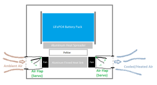
So next topology for me is ALL AIR with BREATHING FLAPS.

Peltier Side A touch Aluminum Block To Battery
Peltier Side B touch Aluminum Heatsink To Outside Air

The trick being to Enclose The Heatsink! And add Flaps!

1636054799301.png

OF COURSE this is too much complication just to heat the battery. I need heating and cooling.
Haven't built this yet.

The fundamental reason it is sound is that the thermal mass of the battery and heat spreader combined will be greater than the thermal mass of the heat sink and volume of air that will be trapped by the servo flaps. The back flow will still occur, it will just not matter anymore.

Of course, this is just One Of Many options, and heating pads are probably best for most members here. If heating and cooling are needed then this topology is worth mentioning in my humble opinion :)

Would probably add some wirewound resistors or heating pad to the Aluminum Heat Spreader to add Cold Weather Guaranteed Performance
iu
 
Forgot to mention, the dotted lines for the entry and exit ports, should have a Mesh or Filter. I will be using 5-10 Mesh Stainless Steel. Finer mesh needs higher static pressure fans and gives more dust resistance. Coarser mesh allows normal low static pressure fans to work but will confer less dust resistance. Maybe even a simple cloth filter too. It's a balance between pressure drop and power usage to move a given amount of air and how much dust needs to be prevented from entering :)
 
From one of the comments on there: " They each draw 3.5 amps at 12.3v or 43 watts" - it's a bit much. Personally I prefer something lower power so the battery temperature changes more gradually. A battery has a lot of thermal mass, and you want to make sure the cells get enough time to properly warm up. With too much heating power, this will be harder to control.
 
From one of the comments on there: " They each draw 3.5 amps at 12.3v or 43 watts" - it's a bit much. Personally I prefer something lower power so the battery temperature changes more gradually. A battery has a lot of thermal mass, and you want to make sure the cells get enough time to properly warm up. With too much heating power, this will be harder to control.
Yeah lol.

It's 35F out here right now and I'm sitting in my camper with the heater running. It's 4 am.

My battery is reading 45F according to the BMS. The heaters are entirely disabled right now.

The only thing I'm still worried about is verifying that reading is even correct. For reference I've got 4x 15 watt heaters and it seems about perfect.
 
Back
Top