diy solar

diy solar

LiFePO4 prismatic cell short circuit current and main circuit protection

One of the issues here is a lack of data from battery manufacturers (both of individual cells and packaged arrays of cells) regarding the short circuit current capability of Lithium Ion batteries.

One thing I am learning is that the short circuit current, expressed in terms of Ah capacity (e.g.10C short circuit current for a 100Ah cell/battery would mean a current of 1000A) is not all that high in many cases. Short circuit currents of 10-30C seem typical in the relatively few cases where I have found data.

For comparison, a good 8D 12V AGM lead acid battery (Lifeline 255Ah) has a short-circuit current of 7300A which corresponds to 28C. BTW, it's easy to find specs. for short circuit current for lead acid batteries.

I suspect the fact that many Li-Ion batteries do not do better is largely a function of the connection between the battery internal electrodes and the terminals. Many wound cells (cylindrical and prismatic) appear to have just a few tabs inserted into the winding, which then connect to the battery terminals. Thus all current has to flow through the relatively flimsy tabs, and within the winding it has to spiral around to get from the tabs to the ends of the winding. Compared with traditional lead-acid cell construction with all plates individually connected to the terminals, this leads to relatively high internal resistance in the metal electrodes alone (not counting the electrochemical part of the cell).

But that is not the only form of construction. For example, Tesla's new 4680 cell has a new connection approach with the whole length of the winding connected to each end of the cell, specifically to reduce internal resistance and losses in that resistance.

This suggests that Li-Ion short-circuit current may be considerably affected by construction.

I would appreciate any thoughts on this, and any data (measured or specified) on Li-Ion battery short circuit current capability.
 
4680 cell has a new connection approach with the whole length of the winding connected to each end of the cell, specifically to reduce internal resistance and losses in that resistance.
indeed!! :D higher specific power
This suggests that Li-Ion short-circuit current may be considerably affected by construction.
indeed.

actively cooling the terminals seems to be one way of dealing with dissipation but since that can be a bit complicated, just lowering connection resistance can work too! more tabs or even one continuous tab would lower resistance of the cell presumably, increasing powahh!!
 
Cell voltage / internal resistance = short-circuit current (at least my best estimate).
People here report cells with 0.25 milli ohm rating, 0.17 milli ohm on test report. From that I get 20,000A

Car batteries with CCA or CA rating (current into 8.5V load), you can calculate internal resistance considering voltage drop from no-load voltage.
Short-circuit current will be about 3x cranking amps.
 
  • Like
Reactions: Dzl
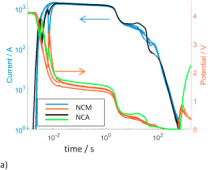
I found this article interesting: https://www.sciencedirect.com/science/article/pii/S037877531730839X

They shorted out NCM and NCA cells at using different external resistances (unfortunately they did not test any LFP cells).

On the most direct shorts, the current chart looked like this (notice the scales are logrithmic).

1638461786999.png

The full short circuit current is only available for a hundreth of a second, and then the voltage sags and the cell continues discharging for another second at an order of magnitude less current, and then it continues discharging for a few more minutes at a lower rate. Of course larger cells would probably have different time durations.

The research paper conclusion says the short circuit current behavior is a result of three different fazes of discharge.
In region 1, the current is the highest (>200 C-rate) and the processes are governed by the discharge of the double and diffusion layers. Then the current drops significantly in the second region, which is likely limited by mass transport resistance(s). Despite the much lower current rate in the 2nd region (on the order of 50 C-rate), the temperature increases rapidly and boils the electrolyte, which in turn leads to internal pressure build up and cell rupture. In our tests, venting, simultaneously with liquid electrolyte release under increased internal pressure, occurred but without thermal runaway and without significant visible smoke. In region 3 the forced discharge of the active material leads to a drop of electromotive force, which in turn causes a continuous decrease of current and potential.

So once the initial open circuit charge of the cell is dissipated, then the current is limited by the speed at which ions can travel between the plates, which causes heat build up inside the cell. Once the structure of the cell becomes damaged, voltage and current tail off. The paper is free to download and has some videos and a lot more detail.
 
I am a little late to the party, but just wanted to add that the BMS FET bank typically has a high enough resistance to prevent 1000's of Amps to flow. This is why you can get by with a small marine grade circuit breaker with a maximum disconnect of 1500A for most 100A BMS. Typically, a 100A BMS with small 6 gauge wires attached will not allow those 1000's of Amps that a LiFePo4 bank can deliver to flow. Which means the current flow will be below the interrupt threshold.

If you parallel multiple battery banks together (my current 60kWh bank can deliver 1150A continuous! Which could easily mean 5000+ Amps for a millisecond), you need a T Class fuse. Especially if you are feeding multiple packs to a very large conductor. That conductor needs to be protected with something that will trip no matter what. I would only trust a T Class fuse for that application.
 
Last edited:
BMS FET bank typically has a high enough resistance to prevent 1000's of Amps to flow. ... Typically, a 100A BMS with small 6 gauge wires attached will not allow those 1000's of Amps that a LiFePo4 bank can deliver to flow.

You are probably right about the FETs.
The 6 gauge wire adds resistance, but the short wires likely not enough. You can look up resistance of the wire. Consider that, not in series with a single cell, but with 4 or 16 cells. Reasonable length of 4/0 to inverter probably similar to few inches of 6 awg, 3 in parallel. I calculated the inverter cables don't limit current much. Resistance was similar to IR of a single cell, much less than IR of a pack.

Difference with silicon is it is a semiconductor, only conducts due to 1 in 10,000 sites doped, typically with boron or phosphorous. Many fewer charge carriers. It looks like a linear resistor up to some current, where the carriers reach "Saturation Velocity". An E-field accelerates them, but they slam into atoms and stop, then have to accelerate from zero. (Makes me think of Star Wars speeders being ridden through a forest.) Above that point, higher voltage but flat current, not increasing.

The silicon will get hot fast. It has some number of Joules it can take, in a short time such that heat can't conduct out fast enough. I've measured circuits with two transistors back to back, one melted. The FET that was on measured significantly lower in resistance than the blob of amorphous silicon that was the failed transistor. (It was an inrush circuit.)

At higher voltage than you're going to see, e.g. 100,000V/cm across a semiconductor junction (think it was about 150V across a small 40V transistor), there is another inflection point in the I/V curve, dielectric breakdown of silicon. That's where the E-field is strong enough to strip electrons off the silicon atom, an all provide charge carriers (rather than just the 1 in 10,000 dopant atoms.) I/V curve turns straight up.

I've seen both those inflection points in data taken with a pulser used to test semiconductors for surge tolerance.

It would be interesting (and important) to know whether a BMS can routinely survive a short circuit, with most of the voltage dropped across its FETs and then they try to cut off current flow. If a contactor is used, no limiting by FETs; we want the contactor to survive while class T fuse blows.
Good points. And it is hard to say how many disconnects a BMS can actually handle. A friend and I were discussing this the other day. We could set up a dead short test with a FET disconnect and repeat it over and over.

Many BMS FET banks are massively beefed up to handle these surges. On older 100A bms, the max current they could handle was 200A. These days, they will put 20X 60A FET's, which can carry and disconnect 1000A over and over. Which means less demand from each FET.

When they fail, at least for me, the weakest FET in the bank will short. Then there is no LVD or HVD. No fire risk for LiFePO4 banks, but if using cobalt based li-ion chemistry, it can catch on fire during charging.

For this reason, I always use the BMS LVD and HVD as last resort methods of safety, and set controller absorption/inverter LVD manually to ensure that the BMS disconnect is not used for this reason. So the FETs are not stressed.

The number one reason that BMS FET's fail is from inrush for capacitors on inverters. Every company I talk to have said that even if they beef up the BMS as much as possible, they will still have a 1/1000 failure rate.

Oh, good point about the contactor. Very true.
 
There are inrush limiter circuits. Power dissipated in fuse, wire, FET is I^2R. In the case of a FET, that can serve as a variable resistance if modulated by gate voltage.
Charging caps with twice the current takes half the time. Twice the current is 2^2 = 4x the power dissipated in a resistive element. But half the time, so 2x the energy deposited. Charging slower reduces energy deposited and heating (of constant-resistance components.) Over enough time, heat flows away.
If the FET is used as a variable resistor to reduce current, because it is higher resistance it also dissipates more energy. Would need to be slow enough to limit temperature rise of junction. A BMS could be designed to do this, especially if it could survive and interrupt the short circuit it sees from charging caps. Open first, then let current bleed through and see if voltage ramps up charging the caps.

One problem with a precharge circuit is if customers get impatient. A project I worked on had multiple power-on circuits daisy-chained. Some circuits would do gradual turn-on, while others would wait until they thought power was good and turn on hard. 22V might be good power in a 24V circuit, but if inrush limiter is gradually raising voltage from 0V to 24V and a customer turns on its own SMPS to charge all its decoupling capacitors, there is still a 2V drop across the inrush limiter FETs. (see my earlier comment about one FET becoming an amorphous blob. The other back-to-back FET of opposite orientation had higher Vgs, was on hard, so undamaged.)

Solution should be inrush circuit completes its work, then says "Power good now!". Ours had that output signal, but customer's power-on signal was fed directly from input power rail. Not even a divided voltage that would have waited for it to be near spec. A suitable resistor divider and RC delay would have been a dumb solution for it.

There are passive inrush limiters, something like an NTC resistor. Common for some types of switching power supplies. May or may not be available for inverters with low idle current and hundreds of amps full load.

With relay (contactor) on BMS, a time-delay relay could automate precharge. Small relay connects resistor, triggers time-delay relay to close high current contactor at predicted good time. Better would be to use measurement of voltage drop across precharge resistor.

If I ever do go lithium, everybody else's bad experiences should benefit me :)
 
I am a little late to the party, but just wanted to add that the BMS FET bank typically has a high enough resistance to prevent 1000's of Amps to flow. This is why you can get by with a small marine grade circuit breaker with a maximum disconnect of 1500A for most 100A BMS. Typically, a 100A BMS with small 6 gauge wires attached will not allow those 1000's of Amps that a LiFePo4 bank can deliver to flow. Which means the current flow will be below the interrupt threshold.

If you parallel multiple battery banks together (my current 60kWh bank can deliver 1150A continuous! Which could easily mean 5000+ Amps for a millisecond), you need a T Class fuse. Especially if you are feeding multiple packs to a very large conductor. That conductor needs to be protected with something that will trip no matter what. I would only trust a T Class fuse for that application.
It sure would be nice to have some references for this assessment. I've long assumed that the BMS leads and circuit board traces and FETs will limit current considerably, but I'd like to see a BMS maker state this based on tests.
 
Lots of discussion of fuse types in this thread but nothing on how Class T fuses work or that they are "current limiting." Or that BMSs are current limiting on high short-circuit currents.

A Class T fuse, is, or used to be, filled with sand that surrounds multiple parallel fuse elements. As the elements melt, they melt the adjacent sand which moves in and blocks any follow-on arc. This can occur well before the short-circuit from a LFP battery reaches its peak, ergo the "current limiting" term.

A BMS in a similar fashion can open in a couple hundred microseconds; well before current reaches it's peak value in the case of a severe short-circuit. Again, "current limiting."
That is all well and good as far as current limiting is concerned. i am not sure what your point is other than to point out the similarity.

My approach to the issue of Over Current Protection is based on risk management principles. I am sure in the preceding 12 pages it has been pointed out that FETS can fail closed. Therefore I would not want to use a FET as my first line of defense for over current protection, especially in the case of a short circuit of a Lithium battery that can discharge enormous amounts of energy very quickly.
 
It sure would be nice to have some references for this assessment. I've long assumed that the BMS leads and circuit board traces and FETs will limit current considerably, but I'd like to see a BMS maker state this based on tests.
Typical 100A bms has about 1mOhm resistance. This alone would limit 12v system short circuit current to about 12000A.
On 48v system we would have 48000A. I can envision mosfet bms capable to disconnect at 5kA but 48kA would be whole lot ballgame.

IF the bms is fast enough it can disconnect before current reaches to destructive levels but most of the BMSes on market are too slow for that. We went trough the maths somewhere in BiduleOhm’s diy bms thread.
 
Replying to Ampster and Matt ..............

My point was just just as I stated (and not included in your extraction). 12 pages of discussion of fuse types and their operating characteristics and ability to quench an arc, and no mention of how a Class T operates or one of it's significant advantages that is the primary reason it is often recommended for LFP batteries.

You also introduced the FET failing closed issue and not depending on a BMS as the only protection. I'm not sure why you introduced that, but since you did, I agree fully. That was touched on in the thread, but surely did not get the attention it deserves. I spent a good part of my 58 years in the power industry working/teaching protection. The first thing I learned and then taught was the need for backup protection. I can't agree more with you there.

Matt, right on. My Overkill BMSs have 11 mv forward voltage drop at about 100 amps load (measured at the board). Hence about 0.00011 "effective" ohms at that current (a tenth of a milliohm). The three #10 leads on each side (a foot long, maybe more) total about 0.00066 ohms. So, that 0.00011 ohms (includes resistance in the circuit board foil) being small compared to the 0.00066 of the wires is unsettling. 0.00011 plus 0.00066 does not suggest enough external current limiting "resistance" to get an LFP down where Will suggests it is. Hence my question to him about where this admonition comes from.

I replied as I did to Will's post* because I'm re-visiting my system protection that includes a CB285 circuit breaker (3kA interrupting at 48V, who knows at 12V) close to each 12V 200 Ah LFP battery. The CB285 is close enough to the battery to qualify as backup to the BMS. The question is whether 3 kA is enough.

Re the BMS being current limiting: The Overkill JDB 120A BMSs open in something like 200 microseconds according to the manual. Plenty fast enough to cut LFP current well below the maximum. I didn't know others aren't as fast.

As an aside, a 48V pack made from four 12V packs that can deliver 12,000A can't deliver 48,000 amps. The short circuit current is still 12,000 amps. Though interrupting 12 kA with 48 volts behind it is a tougher task than with 12V behind it.
 
Last edited:
As an aside, a 48V pack made from four 12V packs that can deliver 12,000A can't deliver 48,000 amps.
How about a 48V pack made from three cells in parallel and 16 of those groups in series 3P16S? that is 840 Amphours and at 20C short circuit current would be 16,800 Amps. Is my calculation correct.
 
Lots of discussion of fuse types in this thread but nothing on how Class T fuses work or that they are "current limiting." Or that BMSs are current limiting on high short-circuit currents.

A Class T fuse, is, or used to be, filled with sand that surrounds multiple parallel fuse elements. As the elements melt, they melt the adjacent sand which moves in and blocks any follow-on arc. This can occur well before the short-circuit from a LFP battery reaches its peak, ergo the "current limiting" term.
I spent a good part of my 58 years in the power industry working/teaching protection. The first thing I learned and then taught was the need for backup protection. I can't agree more with you there.

Perhaps in AC power?

My professional work hasn't been very deep into serious power, but I have had some exposure to issues regarding arcs, fuses and breakers, inrush, etc.


Double check the let-through current curves for class T fuses.
The way I read them, if you have 200,000A available fault current, a 400A fuse will interrupt fast enough that equipment doesn't have to be able to withstand more than about 28,000A. But if hit with 20,000A, let-through is still about 15,000A.

So I think the current limiting is mostly a benefit at the much higher AC current these fuses are rated for.


Although, you mention slow ramp up of current from lithium batteries (meaning they are doing the current limiting, not the fuse.)
Do you have links on the current/time response of lithium batteries to short circuits? All I have to go on is the measured internal resistance on vendor data and BMS measurements that people have posted.

BMS is MOSFETs, so I'm not inclined to trust them. I've seen enough problems with inrush limiter circuits.
 
How about a 48V pack made from three cells in parallel and 16 of those groups in series 3P16S? that is 840 Amphours and at 20C short circuit current would be 16,800 Amps. Is my calculation correct.
Yup. 17ka at 48V could certainly cause some fireworks. Not something to be taken lightly!!! I think I'm glad I stayed with 12V!!! And 400Ah.
 
Last edited:
Perhaps in AC power?

My professional work hasn't been very deep into serious power, but I have had some exposure to issues regarding arcs, fuses and breakers, inrush, etc.


Double check the let-through current curves for class T fuses.
The way I read them, if you have 200,000A available fault current, a 400A fuse will interrupt fast enough that equipment doesn't have to be able to withstand more than about 28,000A. But if hit with 20,000A, let-through is still about 15,000A.

So I think the current limiting is mostly a benefit at the much higher AC current these fuses are rated for.


Although, you mention slow ramp up of current from lithium batteries (meaning they are doing the current limiting, not the fuse.)
Do you have links on the current/time response of lithium batteries to short circuits? All I have to go on is the measured internal resistance on vendor data and BMS measurements that people have posted.

BMS is MOSFETs, so I'm not inclined to trust them. I've seen enough problems with inrush limiter circuits.

I have found LFP short-circuit current graphs. Enter "lithium battery short-circuit current" into your search window and click on "images" and look for something like this link.


This particular one bothers me a bit in that the peak current is indicated to be 1075 amps for a 160 Ah battery. That seems low. Also the current rise time is maybe 5 seconds. That's slower than I recall seeing in the past. Though I can't find that one.

Here's another one. An 8 Ah battery this time. And a faster rise time. Looks to be 2 or 3 seconds. Again, max is about 10C.


If you combine the above with this time-current curve, it seems that the Class T fuse can open in about 10 milliseconds at a current that is about 550% of the fuse rating. If the above examples are correct, a 150 amp Class T on a LFP that can deliver about 10C short-circuit current will interrupt before the current hits its peak (e.g., not long after the current hits about 5C).


If I'm right about the above, the "current limiting" function of a Class T on an LFP battery is a different mechanism than that where it's applied at AC. While the short-circuit current rise time in a worst-case AC short-cicuit (with 1.6x DC component) is about 3 ms, and there is current limiting and a let-thru, with the battery, it seems the fuse simply times out while the current is on its way up.

A year or two ago I thought I was looking at an LFP short-circuit curve that rose faster than the few seconds I'm seeing above. That leaves me a bit unsettled.

The first (left) let-through set of curves in the link below are for an AC & DC rated Class T fuse. It's an AC set of curves, but does indicate current limiting action at currents that we might see from LFP (unless the above recordings are correct). If an LFP DC current can rise more quickly than an AC current, that should only hasten current limiting action I think. So I'm not sure there wouldn't be some current limiting with DC. In these curves a 200A fuse limits a 2000 amps symmetrical available to a peak of 3000 amps. This kind of says a 10kA DC current would be limited by the same fuse .... I think.


Tomorrow I'm going to look further for LFP short-circuit current recordings.
 
Perhaps in AC power?

My professional work hasn't been very deep into serious power, but I have had some exposure to issues regarding arcs, fuses and breakers, inrush, etc.


Double check the let-through current curves for class T fuses.
The way I read them, if you have 200,000A available fault current, a 400A fuse will interrupt fast enough that equipment doesn't have to be able to withstand more than about 28,000A. But if hit with 20,000A, let-through is still about 15,000A.

So I think the current limiting is mostly a benefit at the much higher AC current these fuses are rated for.


Although, you mention slow ramp up of current from lithium batteries (meaning they are doing the current limiting, not the fuse.)
Do you have links on the current/time response of lithium batteries to short circuits? All I have to go on is the measured internal resistance on vendor data and BMS measurements that people have posted.

BMS is MOSFETs, so I'm not inclined to trust them. I've seen enough problems with inrush limiter circuits.
AFAIK batteries wont do much to limit the current rise time. Wiring inductance limits the current risetime but things get smoky pretty fast especially on 48v systems.
Wiring inductance is roughly 1uH/meter, assuming short occurs 1 meter from bms the loop inductance is ballpark 2uH. Lets say bms and battery wiring increases this to 5uH: 50v short results in 10 amps per microsecond current risetime. 200uS breakin time would result 2000A (doable to break with proper design)
On some other bms I have seen claimed 600us response time, this would be 6000A

On 12 volt system the current risetime is only 1/4 of the 48v system and things are lot easier
 
Several LiFePO4 cells (forget if it was 100 Ah or 280 Ah) had ratings IR = 0.25 milliohm, and test results about 0.17 milliohm.
Using that and 3.4V per cell, I came up with 20,000A (regardless of pack voltage) for a single series string.

I found one report of 100 Ah AGM having 4000A short circuit current.
Automotive battery CCA current and voltage ratings indicated about 3000A into short circuit, zero volts.
I figure these don't scale with capacity due to resistance of plates and busbars/terminals.

The LiFePO4 batteries probably have something involving ion transport that drops current below my simple ohms law calculation. A forum member did mention something on the topic.

There was a video of a battery bank being shorted through a lower rated fuse, which interrupted the current just fine. But I calculated the resistance of wire shown was sufficient to reduce current to its AIC rating.

In AC applications, line voltage comes from a transformer rated for a few percent regulation, could be 2.5% above nominal at no-load dropping to 2.5% below at full load. So 5% voltage drop for a 200A transformer means it could deliver 200A / 5% = 40,000A. Wire resistance can further reduce that. Typical residential service I think is about 20kA fault current, so breakers rated 22kA AIC are sufficient. Industrial, can be 100kA and higher.

The class T fuse curves show 0.01 second interrupting up to a few thousand amps, which is 1/2 line cycle at 50 Hz. They don't show min/max time as breakers often do. They don't show what the faster trip times are for 10x higher currents; only the let-through curves suggest that.

For AC applications, one of the concerns is an arc among three phases continuing beyond 1/2 line cycle, when one line crosses zero (so would want to extinguish the arc), because another phase puts current through the same plasma fireball. With a fuse on each phase, the high current is supposed to open the fuses, so you don't get a sustained 0.5 second or so arc continuing to deliver intense heat and UV. (That could be hundreds of times more power than my arc welder, and safety calculations determine protection required based on several calories per square centimeter on the surface of your body.)

With DC from battery, no zero crossings to interrupt arc or help fuse open. AIC rating is 20kA.
With AC, maybe current isn't interrupted in less than 0.01 seconds, but voltage is dropped across the plasma and sand inside fuse. AIC rating is 200kA.
The 600V fuses are several inches long.
 
Several LiFePO4 cells (forget if it was 100 Ah or 280 Ah) had ratings IR = 0.25 milliohm, and test results about 0.17 milliohm.
Using that and 3.4V per cell, I came up with 20,000A (regardless of pack voltage) for a single series string.

I found one report of 100 Ah AGM having 4000A short circuit current.
Automotive battery CCA current and voltage ratings indicated about 3000A into short circuit, zero volts.
I figure these don't scale with capacity due to resistance of plates and busbars/terminals.

The LiFePO4 batteries probably have something involving ion transport that drops current below my simple ohms law calculation. A forum member did mention something on the topic.
There is suprisingly little info "out there" about the shot-circuit capability of prismatic LiFePO4.
Best I have seen is http://pe.org.pl/articles/2017/5/13.pdf but I just find it hard to believe that large prismatic cells are limited to apprx 6C

I could measure one myself but only LiFePO4 cells I have are 18650 cylindrical A123 high current cells that happily deliver 30C at 2.5 volts and probably roughly 100C on short-circuit :cautious:
The paper you referenced is clearly the source of the images I linked to above (that I randomly found on the web). It would be nice to have some other reference with similar results. I found a half dozen papers that might contain that but most were not accessible without some login or didn't sound promising enough to download.

The #1 battery shown in Figure 1 of the paper looks to be a Calb battery very similar to the SC-200 Calb batteries in my system. Kind of reassuring I guess. Presumably the author didn't use 12 feet of #6 wire to his short-circuit switch. I didn't see anything on his test setup. I'll look closer when time permits.

 
I will do my best to be sure it doesn't happen again. You are welcome to learn from my mistake or make it yourself.

I think most of the aluminum melted and exploded off of the terminal immediately. But that didn't break the connection.
The stud burnt off and disintegrated. The busbar melted. All that still didn't break the connection.
The arch didn't stop until I picked up the ratchet. I don't know what would have happened it I didn't remove the ratchet.
I suspect it would have burned everything possible until there was nothing left to arch to.

I shorted on half of a 48V battery. The stud nuts seized on the cells that were involved in the short.
Since the terminal is destroyed on one cell, I can't use it. The other cells seem to be fine.

So, this lightning bolt from hell only cost me about $100. But it reminded my of the ticking time bomb I have in my garage.
I have to do what I can to reduce the likelihood of this happening again. And it seems like I should try to warn others.
But so far no one wants to hear my warning. They think I'm a party pooper. I'll give up soon.
right on buddy, I think too many people are carrying over their lifelong experience with AGM and autos, who has done a short messing with cars, mostly its small wiring/screwdriver etc bit of a flash but never a sustained arc AFAIK. But a bank of Lions well , whole different scene, and they look so innocent dont they, you dont get a shock or anything, so get complacent till the worst happens. Anyone know how to extinguish an arc? My guess bucket of sand on hand, water? Perhaps a friendly stick welder could help if he has a dc stick welder (most modern ones are). Someone need to try it out Please and let us all know
 
I've more or less given up trying to get the actual SCCR for my battery. It's been suggested to me that the battery BMS might be built to limit the SCCR regardless of what one might calculate - but who really nose? My inverter mfg wants me to use a Class-T but when I quiz them closely they concede that the MRBF will be okay. Sounds like we're chasing the same bunny around the same bush. I'm going with the MRBF.
The Nose Knows! To my knowledge, a BMS can not be made to restrict the SCC of a battery. They are electrical devices (Usually MOSFETS) and WILL burn up when their specs are exceeded. SCC is a CATASTOPHIC failure of the battery internals.

I find it funny that people are spending thousands on batteries, chargers, buses, inverters, cables, etc. but baulk at spending less than $100.00 USD for a fuse that may save most of their investment in the case of a failure.
Indeed I have been banging on about this very concern. Such trivial attention is given to the design of the dc distribution system . Most have little idea of whats needed to break a full load current from an array of panels on a full sunny day. I got the collective yawn when I proposed old school large knife switches (used by millions throughout far east). Distance quenches ELV arc flashes but the switchgear and fuse mafia dont want you to know this.Screenshot 2024-03-02 072646.png
 
Thats w
AFAIK class T fuse is expensive because of the fast acting and "current limiting" feature.

NH blade fuses are like 10 usd per piece and often rated 40kA 250 VDC or 80 kA 440 VDC
That is what I use. A fraction of the cost of class T but they do the job perfectly with the same AIC capability.
It just shows what a rip off Class T fuses are
 

diy solar

diy solar
Back
Top