Have you heard of any reports of a LFE cell that has exhibited thermal runaway? I am being sincere here, not sarcastic.Yeah, still a very safe chemistry, but you need to take care regardless. I have seen lead packs go into thermal runaway, and that can definitely start nearby stuff on fire.


You are using an out of date browser. It may not display this or other websites correctly.
You should upgrade or use an alternative browser.
You should upgrade or use an alternative browser.
Lishen 272AH thread?
- Thread starter nebulight
- Start date
It's pretty obvious from the red glow it was NOT fully discharged. The liquid electrolyte inside is a hydrocarbon, get it hot enough to vaporize, and indeed a spark will ignite it (or perhaps just the heat from the not discharged cell that is now shorted). Just because you melted the terminals off doesn't mean the cell is discharged. The long and short of it is, LiFePO4 is the safest lithium chemistry available. Use a fuse. I am not sure what the electrolyte is, but it looks chemically related to Teflon, so I would stay the hell away from the smoke.@HighTechLab posted the following in his YouTube comments:
I think the gasses only ignited because when I sent the spike through it the second time, it cased some level of internal shorting that made a spark that ignited the electrolyte that was being vaporized.
I don't know if he has read this thread but maybe he will stop by and comment here.
REPLY
Have you heard of any reports of a LFE cell that has exhibited thermal runaway? I am being sincere here, not sarcastic.
I have never seen/heard of it happening in the wild. Like all lithium cells, they can experience thermal runaway. However when this occurs the electrolyte boils off, and the cell usually stays below the ignition temperature of the electrolyte. Once the electrolyte is mostly boiled off, the runaway self terminates. The data indicates that this will occur between 115-160C depending on the cells design. In some cases during oven testing cylindrical cells would peak at 350C, but typically it was much lower.
Its pretty difficult to trigger a thermal runaway in an LFP cell, as you need to get the cell up to that temperature, which would require really high voltages, or downright insane currents.
I'm sure it is possible, just not likely.Have you heard of any reports of a LFE cell that has exhibited thermal runaway? I am being sincere here, not sarcastic.
stobbie
New Member
- Joined
- Aug 25, 2020
- Messages
- 49
To answer all questions..
The charger was connected through an extension cord, because there was no mains power connected to the camper.
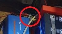
It is circled down left in the picture. It is a Chinese charger, server PSU converted to charger, 50 amps but set to 30. Connected with sillicone wires with crocodile clamps, directly to plus pole of batterypack, and minus connected to minus of bms with a 100Amp fuse in the line.
Rest of camper was disconnected from mains and from the batterypack, so there was no power on anything. The big victron device is a 220v converter but not connected.
It looks like the hottest point has been around where the plus clamp was. Then heat went to the left were the unconnected victron device completely melted..
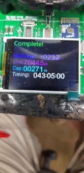
The four cells from the top had 0 volt after the fire, the four lower cells had 3,28v after the fire. I have connected these four as a pack yesterday and fitted another BMS and although the plastic has been melted a little, there seems nothing wrong with them. I should do a capacity test again. But my main big charger is gone now, so I will have to wait for a new one..

The charger was connected through an extension cord, because there was no mains power connected to the camper.
It is circled down left in the picture. It is a Chinese charger, server PSU converted to charger, 50 amps but set to 30. Connected with sillicone wires with crocodile clamps, directly to plus pole of batterypack, and minus connected to minus of bms with a 100Amp fuse in the line.
Rest of camper was disconnected from mains and from the batterypack, so there was no power on anything. The big victron device is a 220v converter but not connected.
It looks like the hottest point has been around where the plus clamp was. Then heat went to the left were the unconnected victron device completely melted..
The four cells from the top had 0 volt after the fire, the four lower cells had 3,28v after the fire. I have connected these four as a pack yesterday and fitted another BMS and although the plastic has been melted a little, there seems nothing wrong with them. I should do a capacity test again. But my main big charger is gone now, so I will have to wait for a new one..
I'm no expert, but I believe the correct place to have put the fuse would have been at the total battery +'ve terminalThe charger was connected through an extension cord... It is a Chinese charger, server PSU converted to charger, 50 amps but set to 30. Connected with sillicone wires with crocodile clamps, directly to plus pole of batterypack, and minus connected to minus of bms with a 100Amp fuse in the line.
...
It looks like the hottest point has been around where the plus clamp was.
Then to connect the charger to the fused terminal, like these
stobbie
New Member
- Joined
- Aug 25, 2020
- Messages
- 49
In that picture you can my charger crocodile clip. I've charged an discharged lots of packs like this on my test bench without any problems, although the clip always got hand warm.
My fused terminal, something like in your link is in my negative side. I don't think plus or minus fused would make a difference?
My fused terminal, something like in your link is in my negative side. I don't think plus or minus fused would make a difference?
MullerEnergy-Australia
New Member
- Joined
- Dec 10, 2020
- Messages
- 95
Does anyone have a good vendor for <$70 prices?
Also, are there any spacers for Lishen batteries that anyone can recommend?
Also, are there any spacers for Lishen batteries that anyone can recommend?
Hi, sorry for the post from the outsite. Until now I am a quiet and amazed reader of this thread.
If the alligator clip gets too hot and the insulating plastic melts at this point, it can of course also melt the protective film of the cells. The housings of the cells are probably negative. The terminal and clips can thus create a short circuit between the housing and a positive pole. The positive pole would be in the form of the pole of the first two parallel cells. So I can well imagine this mistake.
The Problem of croc clips is, that they can loosen quickly an the heat rises.
For me it was a shortcut of the first 4 cells because of the 0V of them.
The threaded rod between the red battery holders is another possibility for a shortcut. The wires in the photo were right next to it - really close.
In both cases no fuse would help for anything.
The safest feasible would be a fuse between each cell. After all, possible short-circuit power of a cell is a cause of fire in itself due to the very low internal resistance. But i have never seen such an installtion.
MullerEnergy-Australia
New Member
- Joined
- Dec 10, 2020
- Messages
- 95
Has anyone heard that Lishen is releasing a 280Ah battery as well? One supplier that I spoke to has different prices for 272Ah and 280Ah Lishen. Or do you think they just sort the batteries by capacity?
He sent me a spec sheet as well.
He sent me a spec sheet as well.
Attachments
My first instinct was to say it was unlikely, I've never heard of a Lishen 280 (and many grey market sellers mislabel the 272 as 280 at least some of the time). But looking at the datasheet it looks genuine (and is dated January 2021, as opposed to 2019 for the 272). Dimensions look identical, IR is somewhat higher, strangely weight is incrementally lower.Has anyone heard that Lishen is releasing a 280Ah battery as well? One supplier that I spoke to has different prices for 272Ah and 280Ah Lishen. Or do you think they just sort the batteries by capacity?
He sent me a spec sheet as well.
Twas
New Member
- Joined
- Sep 22, 2020
- Messages
- 9
Stobbie,
I have followed this thread since the beginning of it. I also bought one of the same power supplies as you did, but off Ebay. Mine took months to get here but it showed up about a week ago. China to the US, Florida to Central America and I got it. I'm really sorry for your loss as everyone else and very concerned because we are all looking for what really caused this. Many of things mentioned could have been the core cause and or a combination of them. I have my two cents worth as well.
Here is a pic of my power supply taken today. Did yours have the same color control box on it?

Image below from your Aliexpress link:

On Youtube there are many vids on how to mod this type and many other server power supplies. Most of us realize that the quality of parts used in many Chinese made or modded products are very poor, though not all. I have a lot of Chinese products that I'm very thankful to have.
In short this mod takes removing a resistor and adding a potentiometer and some replace one or more caps based upon voltage outputs.
For those of you that don't know this power supply from Aliexpress it has a nice display added to the top of it which shows amps and volts. There is a black dial which supposedly changes amperage on the bottom left side of the control box in this pic. On the bottom right is a potentiometer that is recessed and you can't see in my pic, but the Ali pic shows it. That one is for voltage.
Today I did basic testing of it on my bench. I have put up to a 22 amp load on it at 14.6 volts for about 10 min. The amperage adjustment does very little from what I have found though while adjusting my load testers and increasing the load the power supply kept up well.
Where am I going with this? I opened up the additional white control box. First thoughts was not bad and there are actual things inside that look like it really does something. I did not check the values of the potentiometer for wattage and resistance though I will if any of you feel it's needed. I opened the power supply as well though not fully because I would have had to un-solder multiple wires and I didn't have time. I can tell you that the solder work on the power supply side is very poor. Especially the only wire that goes to the left side of the power supply in this picture.
You mentioned multiple times you were pushing 30 amps at 13.6v during the charge. The power supply is rated at a max of 60 amps but only 12v. Yes that is only about 10% over but again the design was for 12v. Many of these power supplies can be pushed way over their rated voltages even to the point of damaging them. From what I read you then need to change the caps on that side of the circuit to be able to handle these higher voltages. This brings up the following point:
1. If the control box they add on to this unit has any issues with the resistance of that potentiometer it could possibly go a few or even many volts over your setting.
2. Check out what the seller says: (I copied this directly from Aliexpress)
a.The first step: the charger should not be connected to the battery, turn on the power, adjust the voltage knob to adjust the voltage, refer to the voltage display above the display screen My comment: (this is the pot, not the knob and I'm sure you know that)
b. Adjust the current to a minimum. After connecting the battery, adjust the current from small to large and adjust to the current you need. (In the charging process, it is not allowed to adjust the voltage knob again, otherwise overcharge or undercharge will occur)
That is a key point. It would appear that if you adjust the voltage after you have connected the battery the displayed voltage will no longer be correct and the output voltage could be higher than what is displayed. This makes perfect sense. The power supply is set at a voltage and though you adjust it higher or lower you may not see the change due to caps and the circuit design or a few other variables.
I tested this theory but only for a few minutes and did not come up with anything conclusive. But it makes you wonder why both the seller on Ali and Ebay mention the same thing.
I feel these are extremely low cost high output power supplies that are being used for something other than their initial design and the workmanship is horrible. From what I see this could easily have been another possible option which caused something to go wrong.
Can these be trusted? I will trust them but only with a high voltage disconnect relay / solenoid so in the event it decides to go over voltage the device will be disconnected from AC.
If any of you have anything further that you would like tested let me know. Stobbie, same goes to you. I would be happy to run tests. And, I surely don't recommend 50 amps on these due to higher voltages in turn you exceed max wattage output or close to it.
If I'm all wrong in this evaluation or completely missed something, well I tried.
I have followed this thread since the beginning of it. I also bought one of the same power supplies as you did, but off Ebay. Mine took months to get here but it showed up about a week ago. China to the US, Florida to Central America and I got it. I'm really sorry for your loss as everyone else and very concerned because we are all looking for what really caused this. Many of things mentioned could have been the core cause and or a combination of them. I have my two cents worth as well.
Here is a pic of my power supply taken today. Did yours have the same color control box on it?
Image below from your Aliexpress link:
On Youtube there are many vids on how to mod this type and many other server power supplies. Most of us realize that the quality of parts used in many Chinese made or modded products are very poor, though not all. I have a lot of Chinese products that I'm very thankful to have.
In short this mod takes removing a resistor and adding a potentiometer and some replace one or more caps based upon voltage outputs.
For those of you that don't know this power supply from Aliexpress it has a nice display added to the top of it which shows amps and volts. There is a black dial which supposedly changes amperage on the bottom left side of the control box in this pic. On the bottom right is a potentiometer that is recessed and you can't see in my pic, but the Ali pic shows it. That one is for voltage.
Today I did basic testing of it on my bench. I have put up to a 22 amp load on it at 14.6 volts for about 10 min. The amperage adjustment does very little from what I have found though while adjusting my load testers and increasing the load the power supply kept up well.
Where am I going with this? I opened up the additional white control box. First thoughts was not bad and there are actual things inside that look like it really does something. I did not check the values of the potentiometer for wattage and resistance though I will if any of you feel it's needed. I opened the power supply as well though not fully because I would have had to un-solder multiple wires and I didn't have time. I can tell you that the solder work on the power supply side is very poor. Especially the only wire that goes to the left side of the power supply in this picture.
You mentioned multiple times you were pushing 30 amps at 13.6v during the charge. The power supply is rated at a max of 60 amps but only 12v. Yes that is only about 10% over but again the design was for 12v. Many of these power supplies can be pushed way over their rated voltages even to the point of damaging them. From what I read you then need to change the caps on that side of the circuit to be able to handle these higher voltages. This brings up the following point:
1. If the control box they add on to this unit has any issues with the resistance of that potentiometer it could possibly go a few or even many volts over your setting.
2. Check out what the seller says: (I copied this directly from Aliexpress)
a.The first step: the charger should not be connected to the battery, turn on the power, adjust the voltage knob to adjust the voltage, refer to the voltage display above the display screen My comment: (this is the pot, not the knob and I'm sure you know that)
b. Adjust the current to a minimum. After connecting the battery, adjust the current from small to large and adjust to the current you need. (In the charging process, it is not allowed to adjust the voltage knob again, otherwise overcharge or undercharge will occur)
That is a key point. It would appear that if you adjust the voltage after you have connected the battery the displayed voltage will no longer be correct and the output voltage could be higher than what is displayed. This makes perfect sense. The power supply is set at a voltage and though you adjust it higher or lower you may not see the change due to caps and the circuit design or a few other variables.
I tested this theory but only for a few minutes and did not come up with anything conclusive. But it makes you wonder why both the seller on Ali and Ebay mention the same thing.
I feel these are extremely low cost high output power supplies that are being used for something other than their initial design and the workmanship is horrible. From what I see this could easily have been another possible option which caused something to go wrong.
Can these be trusted? I will trust them but only with a high voltage disconnect relay / solenoid so in the event it decides to go over voltage the device will be disconnected from AC.
If any of you have anything further that you would like tested let me know. Stobbie, same goes to you. I would be happy to run tests. And, I surely don't recommend 50 amps on these due to higher voltages in turn you exceed max wattage output or close to it.
If I'm all wrong in this evaluation or completely missed something, well I tried.
Last edited:
Kerry downunder
New Member
- Joined
- Sep 28, 2020
- Messages
- 41
Where was cell photo ~659 , What position from the top of assembly ?that is a busbar for the negatives.. But was disconnected at the time of the fire.
Curious if anyone knows how deeply these cells have been tapped. I don't have my cells in-hand yet but I'm trying to get all of the component parts ready for when they show up. I have a relatively tight enclosure and will need to be careful with the length of the M6 studs I order.
I'm guessing there is some variability in how deep they have been tapped depending on the seller (and maybe from batch to batch from the same seller) so this may be a moot question (if that's a thing) - for what's it's worth, my order is coming from Shenzen Luyuan Technology.
Thanks!
-uberpixel
I'm guessing there is some variability in how deep they have been tapped depending on the seller (and maybe from batch to batch from the same seller) so this may be a moot question (if that's a thing) - for what's it's worth, my order is coming from Shenzen Luyuan Technology.
Thanks!
-uberpixel
MullerEnergy-Australia
New Member
- Joined
- Dec 10, 2020
- Messages
- 95
Not very deep! Mine are only around 6mm.Curious if anyone knows how deeply these cells have been tapped. I don't have my cells in-hand yet but I'm trying to get all of the component parts ready for when they show up. I have a relatively tight enclosure and will need to be careful with the length of the M6 studs I order.
I'm guessing there is some variability in how deep they have been tapped depending on the seller (and maybe from batch to batch from the same seller) so this may be a moot question (if that's a thing) - for what's it's worth, my order is coming from Shenzen Luyuan Technology.
Thanks!
-uberpixel
Same here, also got it to ~6mm on the Lishen cells I just received.Not very deep! Mine are only around 6mm.
Okay - thanks. That's not a lot of threads to work with... I will plan accordingly. Also provides further confirmation that using studs (grub screw backed off 1/2 turn) instead of bolts may give me the best chance to use all available threads rather than trying to find the perfect length bolt/washer/terminal stack height.Not very deep! Mine are only around 6mm.
-uberpixel
Similar threads
- Replies
- 17
- Views
- 850
- Replies
- 105
- Views
- 9K
- Replies
- 8
- Views
- 2K
- Replies
- 20
- Views
- 2K
- Replies
- 65
- Views
- 5K