diy solar

diy solar

LVX6048 Burned up on day 1 searching for cause

DENWA

New Member
Joined
Sep 22, 2019
Messages
146
My dad and I installed this LVX6048 Saturday afternoon. We could not get the WIFI to connect to the APP as the setup reported the WIFI module on the LVX6048 could not communicate with the inverter. All else was working well.--FYI--One annoying problem on these others have reported here is the settings require one at a time be saved by backing out of the program screen. Yes each setting. Very painful.

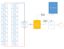
Per the booklet we setup 2 strings of 10 series panels. Measured the voltage on each string open circuit to be about 376VDC. Ran separate strings to the inverter and combined them into one 376VDC 5KW PV input. I guess I was a little surprised they have 1 PV input for a split phase 6kW inverter--Yes I double and triple checked the wiring and voltage.

We were very pleased with its performance as we were seeing 319VDC on the inverter while reporting ~3.3kW at the peak of the mid day Sunday.

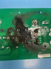
We went for a drive down the street Sunday late afternoon to come back to the inverter smoking. Test showed the PV input was a dead short.

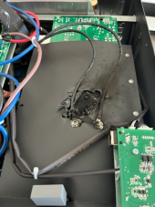
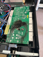
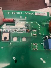
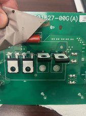
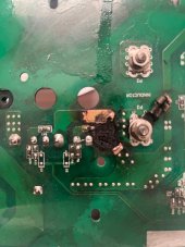
I brought the unit back to my house and took it apart. Pictures attached showed the MPPT unit is destroyed. Tested with My 48V battery stack and connected to my AC power and all other functions seem to be in working order.

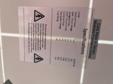
Pictures attached show setup, internal damage and the label on the solar panels we used.

My main concern is how this happened. As always I welcome your thoughts or questions.
 

Attachments

  • solar.png
    solar.png
    85.7 KB · Views: 115
  • Capture.JPG
    Capture.JPG
    14.4 KB · Views: 121
  • download (1).png
    download (1).png
    475.9 KB · Views: 119
  • download (2).png
    download (2).png
    554.2 KB · Views: 122
  • download.png
    download.png
    313.4 KB · Views: 120
Looks like you have a Warranty situation for a faulty AIO. Based on the numbers you give you should not have exceeded any of the units specifications for Max PV voltage of 450v nor the Max amperage of 27a.
 
OK I'm willing to accept conspiracy theories here too. ?

I'm just worried I missed something and when parts arrive from Watts24/7 this could happen again. Then what do I do?
 
OK I'm willing to accept conspiracy theories here too. ?

I'm just worried I missed something and when parts arrive from Watts24/7 this could happen again. Then what do I do?

“You know," said Arthur, "it's at times like this, when I'm trapped in a Vogon airlock with a man from Betelgeuse, and about to die of asphyxiation in deep space that I really wish I'd listened to what my mother told me when I was young."
"Why, what did she tell you?"
"I don't know, I didn't listen.”​


― Douglas Adams,

Hard to know it you missed something in your setup without being there to look at it.
 
Looks like you did everything right as far as I can see, let's just go with a faulty mppt for now
 
...and combined them into one - was the combined voltage 376 or 752v?
any chance polarity was reverse?
not sure of your location, what was the overnight low temperature ? (unlikely to matter actually, just dotting I's and crossing T's)
Some of these units do not support grounding DC, was one leg of the PV DC connected to ground, does this unit support this?
-thats all I can think of that doesn't involve warranty issue.
Thanks for the checklist.

376V and 375V Open circuit strings were combined and double checked to be 376VDC. Polarity was checked before and after connection to match the PV1 markings. Unit was operating normally Saturday Afternoon and Sunday which was very nice sunny but ~32F (0C) day with Unit face reporting ~319VDC on the PV1 input at nearly 3kW input power.

Good question but no the DC return leg (Negative) of the PV1 input was not connected to GND, EGND or Neutral

BTW-- I dissembled the board that burned up.

Found out some really cool things and I think i will repair it for a spare.

I may do a write up on it tomorrow.
 
What did Ian of 247 say about your board failure? He is pretty good at customer service.
That board looks like inverter section.
Can you provide the straight shots pictures of the whole AIO showing all the boards, and top and bottom side of that burnt out board?
 
Here is my amateur's analysis of the MPPT circuit on the LVX6048 PV input:

Removed Heat sink to expose switching components on the PV input board.
Notes:

1. Board is Conformal coated very nicely and its hard to remove with Isopropyl and a brush. Good JOB with the moisture barrier!

2. a 1uF 630V capacitor and LARGE Common mode choke sit on the front end-- This cap will be important later.

3. The circuit next to CM Choke looks to be the driver for the switching components with its own built in transformer power supply etc.

4. Devises under the heatsink are isolated by a thin thermal pad 2 parallel Didoes and 2 Parallel IGBT Transistors I was expecting a MOSFET!

5. Looking at the board layout and markings of the burned connections make this circuit look like a simple BUCK topology. Which makes sense 120-420V MPP rage feeds in to this board at 6kW ( Up ~50Amps at 120V) then kicked down to a BUS Voltage distributed through the remainder of the system. IDK what voltage this is but I will see after the repair parts come in.

6. Burned traces are the Transistors junction with the off board output side inductor. This indicated and matches the measurement of shorted damaged C-E on Q1 Transistor. Q2 and Both diodes look good. ROHM Part 650V 80A Field Stop Trench IGBT! 2 in parallel would indicated a 100 degree C current draw of 160Amps contin. capable through the switcher. I don't know what the bus voltage is but I can assume near battery voltage which 48V would make these more than capable parts
Datasheet

7. Here is where the problem starts! 630V Capacitor will explode much above 630V, IGBT's rated for 650V tells me its unlikely this saw overvoltage, but likely it was switching driver failing or a bad part from Rohm.

I will get a picture of the CM Choke and Driver CKT along with the Diodes D1&2
 

Attachments

  • thumbnail_IMG_1394.jpg
    thumbnail_IMG_1394.jpg
    163.2 KB · Views: 50
  • thumbnail_IMG_1393.jpg
    thumbnail_IMG_1393.jpg
    136 KB · Views: 49
  • thumbnail_IMG_1392.jpg
    thumbnail_IMG_1392.jpg
    169 KB · Views: 49
  • thumbnail_IMG_1388.jpg
    thumbnail_IMG_1388.jpg
    178.5 KB · Views: 50
What did Ian of 247 say about your board failure? He is pretty good at customer service.
That board looks like inverter section.
Can you provide the straight shots pictures of the whole AIO showing all the boards, and top and bottom side of that burnt out board?
Ian hasn't commented at all. He charged me $68 to ship a new PV input board UPS Ground.

I'll take more pictures today.
 
He charged you to ship out a warranty replacement ???

To me, that looks like a simple dry joint started to arc. I'm sure the IBGT got pissed off and blew up.
 
He charged you to ship out a warranty replacement ???

To me, that looks like a simple dry joint started to arc. I'm sure the IBGT got pissed off and blew up.
Now that you mention it I did see a poor solder joint on the collector ( center pin of Q2)
 
This looks like a bad solder joint to me. The only damage to the top of the board under and around the component is the burn through from the bottom. The bottom shows more severe burning of that output trace and the board under it. If the solder joint was poor, the resistance would increase, which would increase the temperature, which would increase resistance, back and forth until you are melting things. I think the transistor shorted as a result of the heat.

If the transistor had shorted and caused this, I would expect to see melting on the ground side of that short circuit too, and more equal trace damage top and bottom. Plus the other transistor would probably have been damaged from the overload.
 
The replacement part should have been free. Though the whole unit should be replaced by Warranty. Using your expertise to fix a manufacturing error saves them a lot of money.
I don’t have an issue with the shipping fee but diy repairs on something under warranty has three outcomes. It works, it doesn’t work or it works but blows out again.
I have played against those odds and while it typically works out, there are times when it doesn’t and I have to pay again to ship out the whole unit.
 
Be careful if you repair and keep it as a spare as burnt PCB is (very) conductive. If it's just smoke/vaporised metal stains then you can clean them and you're fine, otherwise you need to remove all of the burnt material and reconstruct the traces with some rigid wire ;)
 
Back
Top