diy solar

diy solar

MPP Solar LV6548 - Suitable conduit option for the PV inputs - With Pics

Samsonite801

Solar Wizard
Joined
Oct 15, 2020
Messages
2,994
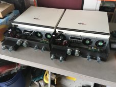
I FINALLY got around to building my wall and hanging my inverters in the last couple weeks. I never did like the PV inputs being MC4 connectors on the bottom of the units, because it didn't lend itself well to the idea of going all conduit.

So after thinking on it some, I noticed that the LV6548's come with these nifty little extension boxes, but they were made to be screwed onto the bottom-right end of the inverters, to extend the battery terminal conduits (for SOME reason unknown to me).

So I got to thinking, maybe I could just use those boxes, and fashion them to the lower-left end of the inverters, right under the PV inputs, and get rid of the MC4's, and just put spade connectors right on the ends of my PV wires and plug them directly into the input boards.

So far the idea is working out good, haven't gotten to the wiring yet, but the box fits, there was one threaded hole that happened to be there already, just had to drill 2 more holes, put nuts/screws on them, and use my die grinder to notch the upper-right corner of the box so it would clear the 1" conduit fitting to the right of it.

Anyways, in case anyone with the LV6548's wants to try it, here are some pics...


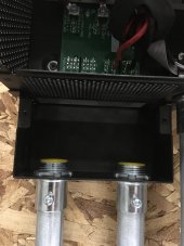
Mockup with boxes at lower-left corner sitting there to test fit:
1691125578464.jpeg


Permanently removed the old MC4 connector mounting plate:
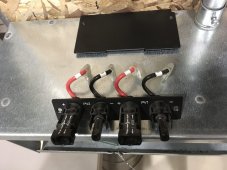
1691125679847.jpeg


Drilled 2 holes, one on each side, right side already had one suitable threaded hole that happened to line up perfectly to where I wanted the box to sit, some minor notching was needed around the box's flange mount to clear the 1" conduit to right of box:
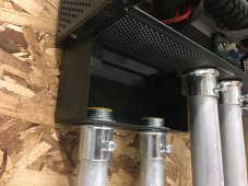
1691125842123.jpeg

Can't see the notching work very well here, but it is mostly on the flange near where the screws hold the flange to inverter case, and a little notch on the corner of the box itself above the cover plate flange mount:
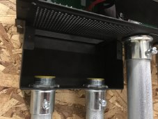
1691125910338.jpeg


You can see the two screws/nuts I added in, and if you look close behind the right-side screw/nut, you can see the threaded screw hole that just happened to line up already (it's the left-side screw for the factory cover plate over the inverter sync board I/O plugs, which you remove anyways for multiple inverter stacking). It was nice, because I put in the factory style screw into that hole, and it held the box in perfect spot to line up the box in perfect position to drill the other two holes:
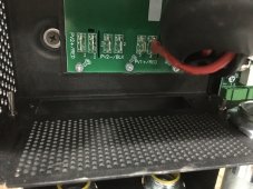
1691126095885.jpeg


Different angle:
1691126139719.jpeg


Cover plate notched slightly too (upper-right corner):
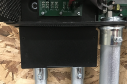
1691128076250.png

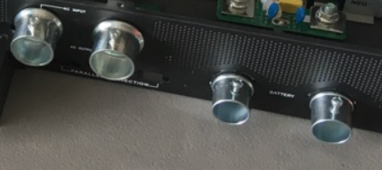
Finished product (not including wiring):
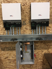
1691126260569.png

1691126458439.png


Now you can have conduit on every wire run with your LV6548's, took under an hour to do and the boxes are already included with them, just need some tiny nuts/screws (countersink style)...
 
Last edited:
I never thought of mounting the fuses in the gutter way… it would scare me silly if I ever needed to change the fuse…

Your disconnects eliminate the issue of course.
 
I never thought of mounting the fuses in the gutter way… it would scare me silly if I ever needed to change the fuse…

Your disconnects eliminate the issue of course.


I guess one could say the trough can add better protection in case the fuses pop with a bang or something. I haven't actually mounted them yet, but was planning to locate them in there since it's convenient and I don't have much room elsewhere to put them.

Yeah, I just figured that big trough has gobs of extra room in it, so why not, yeah I hope those fuses will never blow either, but there are only 5 bolts to take the front plate off, I might just leave a nut driver sitting near there in case I need to pull it off fast.

Those other breakers/disconnects in the lower DC box are per-battery pack breakers, have 3 now, that box (the MNDC175-X2) only came with 2 175a breakers max capacity, so I ordered a 3rd 175a breaker and modded the box with a die grinder to fit the 3rd one in there hehe...
 
Last edited:
In before the plywood backer police. :cool:

Looking good!!
 
In before the plywood backer police. :cool:

Looking good!!

Thanks! Yeah I know, I got too anxious/impatient and too lazy/cheap to go all the way to town to get the fireproof board (had contemplated it), besides a neighbor gave me that plywood for helping him on something, I just didn't care enough, I just want to get my permanent system going by now. The rest of that wall I built out of old heavy-duty free pallets I took apart. The inverters and DC box are lined up with the screws going into pallet 4x4's, that wall is super sturdy otherwise.

Good thing it's a steel building that equipment wall doesn't even reach close to the ceiling at all, I guess if it does start on fire then it wasn't meant to be so will just build something else hehe.. I haven't lost any sleep over it yet, hopefully nobody cancels me over using plywood facing.

Another neighbor of mine even commented about the plywood too (his uses fireproof board), and I just said yeah sorry, I didn't care enough to worry about it (will just have to tell everyone that now)...

Even here, they don't seem to care if you use plywood for inverter and equipment backing:

I don't even see how any fire originating from inside the inverter, could get outside the metal case of it, unless it burned long enough to melt the case, and I think the Class-T fuses would burn out first (or blow one of the AC breakers first) if there was a short that long or hot...

Anyways, thanks for the heads up about the plywood backer police, point noted and taken :geek:
 
Yeah, I just figured that big trough has gobs of extra room in it, so why not, yeah I hope those fuses will never blow either, but there are only 5 bolts to take the front plate off, I might just leave a nut driver sitting near there in case I need to pull it off fast.
Very nice install, good idea. You should add a hinged door for the fuses, maybe even perspex with an LED across the fuse so you can tell if it ever blows !!!
I don't even see how any fire originating from inside the inverter, could get outside the metal case of it, unless it burned long enough to melt the case, and I think the Class-T fuses would burn out first (or blow one of the AC breakers first) if there was a short that long or hot...
I agree, it might be a gnats cock safer with a fireproof backer but at that point, your problems would be much bigger.
 
Thanks! Yeah I know, I got too anxious/impatient and too lazy/cheap to go all the way to town to get the fireproof board (had contemplated it), besides a neighbor gave me that plywood for helping him on something, I just didn't care enough, I just want to get my permanent system going by now. The rest of that wall I built out of old heavy-duty free pallets I took apart. The inverters and DC box are lined up with the screws going into pallet 4x4's, that wall is super sturdy otherwise.

Good thing it's a steel building that equipment wall doesn't even reach close to the ceiling at all, I guess if it does start on fire then it wasn't meant to be so will just build something else hehe.. I haven't lost any sleep over it yet, hopefully nobody cancels me over using plywood facing.

Another neighbor of mine even commented about the plywood too (his uses fireproof board), and I just said yeah sorry, I didn't care enough to worry about it (will just have to tell everyone that now)...

Even here, they don't seem to care if you use plywood for inverter and equipment backing:

I don't even see how any fire originating from inside the inverter, could get outside the metal case of it, unless it burned long enough to melt the case, and I think the Class-T fuses would burn out first (or blow one of the AC breakers first) if there was a short that long or hot...

Anyways, thanks for the heads up about the plywood backer police, point noted and taken :geek:
It isn't that the plywood can catch fire from shorts or whatever, it is that the installation instructions specify it and will fail inspection if the inspector notes it in the check.
 
I FINALLY got around to building my wall and hanging my inverters in the last couple weeks. I never did like the PV inputs being MC4 connectors on the bottom of the units, because it didn't lend itself well to the idea of going all conduit.

So after thinking on it some, I noticed that the LV6548's come with these nifty little extension boxes, but they were made to be bolted onto the bottom-right of the inverters, to extend the battery terminal conduits (for SOME reason unknown to me).

So I got to thinking, maybe I could just use those boxes, and fashion them to the lower-left end of the inverters, right under the PV inputs, and get rid of the MC4's, and just put spade connectors right on the ends of my PV wires and plug them directly into the input boards.

So far the idea is working out good, haven't gotten to the wiring yet, but the box fits, there was one threaded hole that happened to be there already, just had to drill 2 more holes, put nuts/bolts on them, and use my die grinder to notch the upper-right corner of the box so it would clear the 1" conduit fitting to the right of it.

Anyways, in case anyone with the LV6548's wants to try it, here are some pics...


Mockup with boxes at lower-left corner sitting there to test fit:
View attachment 160958


Took off old MC4 connector mounting plate:
View attachment 160959


Drilled 2 holes, one on each side, right side already had one suitable threaded hole that happened to line up perfectly to where I wanted the box to sit, some notching was needed around the box's flange mount to clear the 1" conduit to right of box:
View attachment 160963

Can't see the notching work very well here, but it is mostly on the flange near where the bolts hold flange to inverter case, and a little notch on the corner of the box itself above the cover plate flange mount:
View attachment 160966


You can see the two bolts/nuts I added in, and if you look close behind the right-side bolt/nut, you can see the threaded bolt hole that just happened to line up already. It was nice, because I put in the factory style bolt into that hole, and it held the box in perfect spot to line up and drill the other two holes. I probably could've put an extra bolt on the left side, but decided I didn't need it really (3 bolts holds it great):
View attachment 160967


Different angle:
View attachment 160968


Cover plate notched slightly too (upper-right corner):
View attachment 160974

Finished product (not including wiring):
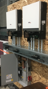
View attachment 160972

View attachment 160973


Now you can have conduit on every wire run with your LV6548, took under an hour to do and the boxes are already included with your LV6548's, just need some tiny nuts/bolts...
Nice job! It looks like something engineer775 would do with a sol-ark install. Very professional.
 
Very nice install, good idea. You should add a hinged door for the fuses, maybe even perspex with an LED across the fuse so you can tell if it ever blows !!!

I agree, it might be a gnats cock safer with a fireproof backer but at that point, your problems would be much bigger.

Great idea, I thought I saw a long hinge around somewhere, just have to remember where I thought I saw that. I might add one at some point.
 
It isn't that the plywood can catch fire from shorts or whatever, it is that the installation instructions specify it and will fail inspection if the inspector notes it in the check.

In my rural county here, they aren't inspecting electrical on outbuildings, only on the houses, at least thus far.

A little Googling came up with this:

"It is up to the local authority what to require. The NEC only says that work be neat and workman like and that equipment be firmly attached to the surface to which it is mounted. It's generally understood that it's impossible to firmly mount anything to drywall, thus a more substantial surface is required. What that is is up to the local authority."
 
Nice job! It looks like something engineer775 would do with a sol-ark install. Very professional.

The inspiration for me to go with a trough, was inspired by Engineer775! I had seen all his install videos a couple years ago, was always impressed with his clean install work, just seem logical for me to go with a trough, since I prefer to keep things tidy as reasonably possible.
 
Last edited:
When I first purchased my LV6548's, I had looked at the circuit board connected to the MC4's and intended to remove the MC4's and run conduit up and connecting to the spade terminals. I don't recall a small extension panel in the boxes. I ended up purchasing a pair of EG4 6500EX's for higher string voltage using conduit for PV wire. Those didn't work out so during a RMA of the original 6500EX's, I installed some temporary MC4's and left out the conduit when I decided to install the LV6548's temporarily with half of the string voltage. When the new 6500EX's arrived, I installed the units one day and removed the units the next day and installed the LV6548's back in with the temporary PV wires. One Youtube viewer mentioned I needed metal conduit but I told him it was temporary until I finished installation of 2 high voltage MPPT's.

Nice neat job on the install, I'll have to go dig thru the inverters shipping boxes and see if the extension box is in there.
 
Nice build, hoping I can get mine to look as clean!

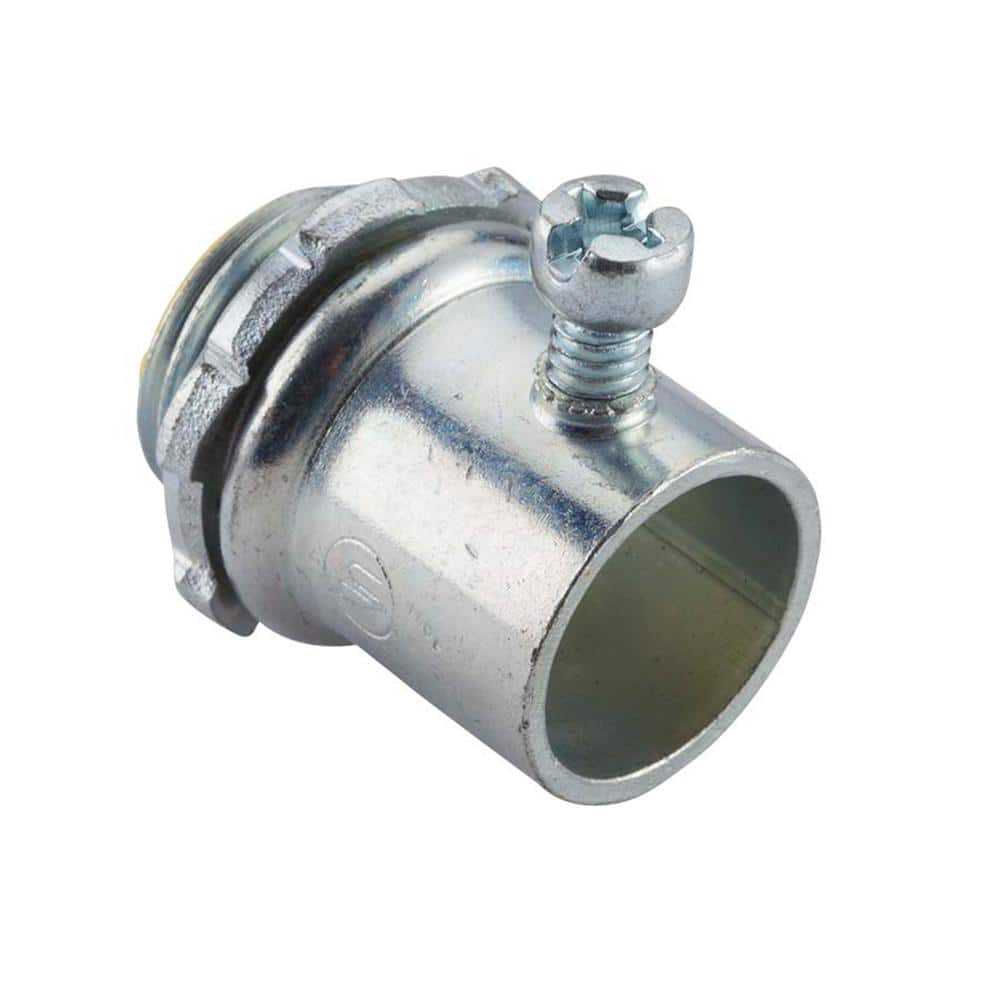
What are these things called that fasten the conduit to the inverter? How did you size them or do you remember the sizing for the LV6548? I need to run conduit from my wireway to my LV6548's

1712964136409.png
 
Nice build, hoping I can get mine to look as clean!

What are these things called that fasten the conduit to the inverter? How did you size them or do you remember the sizing for the LV6548? I need to run conduit from my wireway to my LV6548's

View attachment 209024
Those are EMT set screw connectors.
They also make wet rated with nuts and crimp rings.
 
Back
Top