Logic28
New Member
I have a question for you guys and gals:
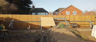
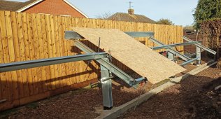
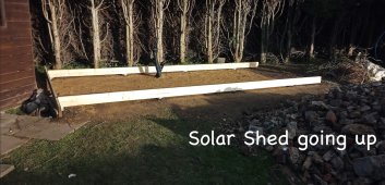
I’m building a ground mount 15 modules PV System with a dedicated detached solar shed for all my Victron goodies.
I have prepared both a combiner box with the three lines each with its own twin fuse, twin surge protector/breakers/reverse diodes plus a separate box with the three isolating switches initially intended to be installed on one of the PV posts.
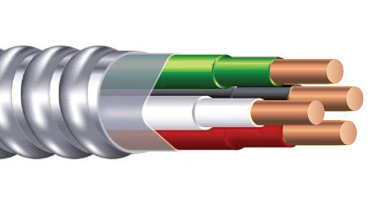
However, looking for the appropriate cable, I came out with the best solution being an armoured 7 ways 10mm each using 6 of them, 2 per string.
Now, is it worth installing the combiner box out in the open next to the isolators or, since I will be adopting individual lines anyway, should I perhaps move the combiner box comfortably inside the solar shed 15 metres away?
In which case, since it’s all travelling inside a 75mm double wall trunking, why not using standard black and red solar cables?

Any comment will be very much appreciated
Many Thanks
I’m building a ground mount 15 modules PV System with a dedicated detached solar shed for all my Victron goodies.
I have prepared both a combiner box with the three lines each with its own twin fuse, twin surge protector/breakers/reverse diodes plus a separate box with the three isolating switches initially intended to be installed on one of the PV posts.
However, looking for the appropriate cable, I came out with the best solution being an armoured 7 ways 10mm each using 6 of them, 2 per string.
Now, is it worth installing the combiner box out in the open next to the isolators or, since I will be adopting individual lines anyway, should I perhaps move the combiner box comfortably inside the solar shed 15 metres away?
In which case, since it’s all travelling inside a 75mm double wall trunking, why not using standard black and red solar cables?
Any comment will be very much appreciated
Many Thanks
")