nahid2k5
New Member
Hi,
I have designed a solar system and soon going to install by myself on my roof top (live in Sydney, NSW, Australia). Here are the specifications,
Please see attached picture for more details on point 7. Also, I followed
for number 7.
Thanks in advance, please provide as many corrections as you can think of.
I have designed a solar system and soon going to install by myself on my roof top (live in Sydney, NSW, Australia). Here are the specifications,
- My grid connection is 3 phase
- My solar system will have 2 branches. each will be 4.8kW micro inverter based connections.
- My micro inverter will be Hoymiles 1600w, 4 Panels MPPT. 3 in each branch, connected to 10AWG trunk (32AMP max).
- I will use 10AWG groudning cable to ground all the panels, rails, inverters. Please advice you expert comments here for this.
- So, finally, there will be 2 AC strings will be coming down to be connected to the grid system. I will connect each AC line to each pahse, so, only 2 phases will be bridged between my solar system and grid pahases. (Why 2 phases? because, that is the max my roof space can support)
- Since, my inverter is 1600w, accepting 4 panels, so, I have decided to use Trina 510W (TSM-DE18M(II)-510W) panels. I followed 1.25 ratio. So, for 400w input, 400x1.25 = 500w to increase max efficiencies for panel to inverter ratio. Please advice you expert comments here for this.
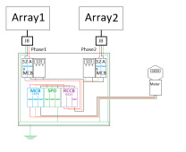
- Now, connection to the grid I have designed as follows - Please advice you expert comments here for this.
- Each AC PV string (Branch1 and Branch2) will first be connected to 2 seperate MCBs (Type B(should it be type C?), 32AMP, 2Pole MCB). So, both hot and nutral will go via the MCB
- Then each branch will connect to individual phase meter (using DDSU666)
- and then hot line 1 and hot line 2 from branch 1 and branch 2 + nutrals (both are now merged together from both branchs - any comments?) and then connected to a RCCB Type B, 32AMP (should it be 63amp?), 3 poles (Phase1, Phase2, Nutral).
- Grid Phase1,2,nutral are connected to MCB (32AMP, Type C, 3 poles)
- Now, other end of MCB and RCCB and joined by bus bar but there will be SPD in between them to protect voltage surge.
Please see attached picture for more details on point 7. Also, I followed
Thanks in advance, please provide as many corrections as you can think of.