diy solar

diy solar

NEMA standard plugs for semi-portable solar?

ksJoe

New Member
Joined
Oct 21, 2022
Messages
20
Location
kansas
I'm building an off-grid solar system for an equipment garage. Its rural, and the county I'm in does not have electrical inspections. Code compliance is not an concern, but safety is. This video got me thinking about the value of my batteries and inverter being portable. I plan to cut up an aluminum server rack and weld it together such that it will sit stable on the floor without being bolted down, holding 2-3 rack mount batteries and the inverter. The idea is, if I ever need a portable power supply, I can unhook it and set in the back of the truck (for example, when we build a tiny house in the next few years).

So - I'd like to have the inverter "plug in" to a distribution panel in the garage.
If there are any norms for what NEMA plugs to use, I'd like to follow the norms.

system details:
12 x 305w Hyandai panels (6 series, 2 parallel = around 250vdc 19 amps),
1 x eg4 3kw 120v all-in-one inverter/charge contorller
2 x SOK 48v batteries

For the 120v line, I'm thinking NEMA L5-30 is appropriate because that's a 30a, 120v, twist lock. I'd get a generator inlet plug for the breaker box in the garage, so the inverter plugs into it like a generator.

I'd like to have some 48vdc things in the garage (security cameras, wifi, etc). That will be 1-2 amps. I'm thinking SAE 2 pin?

What I'm unsure of, is what is appropriate for the 250v / 20a DC from the solar panels? Any 20a rated plug would "work", but I'm wondering if there's any preferred or recommended options.
 
120v generator inlets are uncommon. If you wanted to use a common inlet on the building I would probably use a 50 amp 120/240v twist or Califorinia style.

For the solar connections, MC4 would probably be the most common expectation.
 
120v generator inlets are uncommon. If you wanted to use a common inlet on the building I would probably use a 50 amp 120/240v twist or Califorinia style.

For the solar connections, MC4 would probably be the most common expectation.
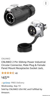
Note: Specs say 500VAC max. I’ve used it to 90VDC for 2 ea big deployable panels in series for my work van. I think I used 10 gauge SOOW cable, that seals off nicely when you tighten down your nut. Use at your own risk. I use this for 40A or less. I’d never max out the specs for any Chinese-sourced for high profit in the US execs pockets junk. I reduce by 50-80% after looking it over and testing it.

Anything where I need more than 40A DC I would go with Anderson connectors. Good stuff on FleaBay.IMG_8264.jpeg
 
Last edited:
I've used 4-prong dryer (30A) an range (50A) cords to temporary testing. That is like a suicide code, except these are UL-1741 GT PV inverters so sync to grid and shut off when unplugged. Also twist-loc, since I had that outside.

I just installed a welder (60A) outlet, which will let me plug in a breaker panel surrounded by outlet boxes with all single or split phase NEMA and twist-loc outlets known to man. Another box will have 3-phase outlets, and some of those split-phase ones so I can test PV inverters that auto-configure 208 vs. 240V based on neutral wire and phase.

Add a redundant ground wire for safety, and think about neutral/ground bond. My inverters get those from grid connection, but the battery inverters will continue operating when disconnected from grid, so need to provide those separately. If my PV panels are mounted and have a ground, that can serve the purpose, but don't operate without inverter chassis grounded and PV panel frames connected to inverter chassis.

If you're feeding house electrical panel from inverter, do that with either a transfer switch or interlocked generator input. For 120V inverter, you can have input plug "Line" fed to a 2-pole breaker for both L1 and L2 of panel, but only with relatively small inverter. 2500W is fine for house with 20A rather than 15A circuit, 3000W a little in the yellow zone but you could get away with it. Higher wattage, you need to determine if you have any branch circuits with Romex (or other) 3 wire plus ground, as in Red, Black, White, bare copper in a single cable. Feeding 120V single phase into both L1 and L2 of such circuits can supply excess current to White neutral, not protected by breakers.

If you feed 120V into L1 only and leave L2 floating, you must turn off all double-pole breakers. Otherwise, 240V loads and 120V loads on the non-powered phase will suffer brownout, could be damaged.
 
Add a redundant ground wire for safety, and think about neutral/ground bond.
I plan to have 1 ground rod in the garage. Solar panel frames, the ground/nuetral buss bar in the breaker box, and the ground connection on the inverter box will all be connected to this same ground rod.

I believe this means that if the inverter has ground-nuetral bond, it will be redundant since the ground and nuetral will be bonded in the breaker box.

If I ever take it out as a temporary power supply, I think I should have the ground/nuetral connected on the inverter, if they're not already.

If I ever use it as a temporary "haul around in the truck" power supply, are you saying I should drive a ground rod and ground it before turning it on?

If you're feeding house electrical panel from inverter, do that with either a transfer switch or interlocked generator input.
I understand this comment to be related to safety issues with grid conneced systems. Its a garage, not a house, but yes I'm using a standard electrical panel. I'm not planning on any transfer switches, lockouts, etc. This will never be grid connected. The nearest grid power is over a mile away, and I would have to pay to run it to my property. The sole source of power is the inverter, so no lockouts necessary. If the solar broke down, I might connect a generator temporarily, but that be done by unplugging the box from the solar, and plugging the generator in its place. If I've misunderstood, please correct me.

Feeding 120V single phase into both L1 and L2 of such circuits can supply excess current to White neutral, not protected by breakers.
good point

if you feed 120V into L1 only and leave L2 floating, you must turn off all double-pole breakers. Otherwise, 240V loads and 120V loads on the non-powered phase will suffer brownout, could be damaged.
understood, but not applicable here. This is 100% off grid, the panel will only have 120v breakers because that's all the power I'll ever have available.
 
I plan to have 1 ground rod in the garage. Solar panel frames, the ground/nuetral buss bar in the breaker box, and the ground connection on the inverter box will all be connected to this same ground rod.

Since some inverters give people a shock though capacitance to isolated PV panel frames, good that they are tied together.

I believe this means that if the inverter has ground-nuetral bond, it will be redundant since the ground and nuetral will be bonded in the breaker box.

Eliminate that redundancy, only bond neutral to ground in one place.
"Ground loops" i.e. redundant connections of chassis to ground network through multiple paths/wires and multiple ground rods I'm not particularly concerned about.

If I ever take it out as a temporary power supply, I think I should have the ground/nuetral connected on the inverter, if they're not already.

If I ever use it as a temporary "haul around in the truck" power supply, are you saying I should drive a ground rod and ground it before turning it on?

Mobile RV/boat inverters have a UL standard where they isolate neutral as well as line from shore power (might still be plugged in, or might be unplugged) and bond neutral to ground.

My Sunny Islands aren't meant to be mobile. I think I'd make an outlet with N/G bond, nothing else, and plug power cord into that to feed it the bond.

GFCI is a good idea for mobile power supply. And inverter chassis bonded to vehicle, as I discovered after unplugging a 12V inverter.


I understand this comment to be related to safety issues with grid conneced systems. Its a garage, not a house, but yes I'm using a standard electrical panel. I'm not planning on any transfer switches, lockouts, etc. This will never be grid connected. The nearest grid power is over a mile away, and I would have to pay to run it to my property. The sole source of power is the inverter, so no lockouts necessary. If the solar broke down, I might connect a generator temporarily, but that be done by unplugging the box from the solar, and plugging the generator in its place. If I've misunderstood, please correct me.

In that case you're find feeding inverter to main lugs, or a backfed breaker (which should be secured against popping out.)
Maybe some day you'll want an interlock so a generator can be used instead. Or, plug either inverter or generator into same inlet plug. Plan accordingly, maybe cord from inverter feeds same 120V leg into both phased of panel, but generator feeds 120/240V split-phase.

good point

understood, but not applicable here. This is 100% off grid, the panel will only have 120v breakers because that's all the power I'll ever have available.

Wired appropriately, no problem.
Usually this is a retrofit.
 
If you have an NG bond in the panel and the inverter then you'll have neutral current flowing over the ground wire between the panel and the inverter. You'd probably not notice this, but it ain't right.
 
So if the inverter (not purchased yet) does in fact have ground/nuetral bond, I should treat my breaker box as a subpanel (I forget the proper term), and keep grounds and nuetrals on separate bus bars. makes sense.

I got a journeyman electricians license back in high school, but that was decades ago and I've forgotten most of the details.

Thanks everyone!
 
Back
Top