diy solar

diy solar

new installation, they say my inverter is bad

onthewall

New Member
Joined
Jul 19, 2023
Messages
9
Location
SC, USA
Sorry to dive right in, but I am a bit frustrated.
I started my solar journey by sourcing all of the components after doing lots of research.

After many road blocks, I decided to get a company to install it and go through permitting and the hassle with the local power company.

So the short of it is... they are saying that the inverter is bad. I disagree and need some perspective from others.

Inverter is an SMA SB 6000TL-US. Yes, it was bought used, but it was in production. Has KW/h showing on the total production line on the display.
Unit will "power on" when the AC is connected. LEDs flash, then after 15-ish seconds, the system goes into a standby type status. The display will light up when you knock, but no production has happened since install.
I have checked the voltage from the string at the round on/off switch box and it is showing around 8 volts. This is before the switch and after (going into the inverter). To me, that says they are in shutdown, or something, and that is not enough voltage to "turn on" the system to start production.
I have looked at the varistors and the whole system, and everything looks clean. No burns, no exploded parts, etc.

Thoughts, ideas? Many thanks and I will be happy to give more info on the system if you can think of something I missed.
 
Last edited:
  • Like
Reactions: BSS
I have checked the voltage from the string at the round on/off switch box and it is showing around 8 volts. This is before the switch and after (going into the inverter).
Welcome!

That's the issue with mix-and-match of used and installers that presumably make more money by selling kit. I'm surprised you found installers that attempt to install used equipment that they didn't supply.

Not sure exactly where you are measuring... What is the voltage of your PV input before the inverter? Presumably more than 8V? If not, sounds like there is a fault with the panels, the dc wiring or you need to remove the snow off the panels ;) If PV voltage is OK, you'll need to probe and trace through to see what's not getting where. But careful of high voltages ⚡
 
You have just discovered the BIG disadvantage of suppling equipment to be furnished by others. As an installer myself of electrical equipment if you buy it, I don't warranty it nor troubleshoot it.
 
yes. hind sight is 20/20. i appreciate the reminder. this whole thing has been a debacle.

I do not see any other disconnect. If there is one, it is hidden under the panels or somewhere i can't see it. There is only the AC switch box, the inverter, and the DC disconnect on the bottom of it. The strings are wired directly into it. That is where I am measuring the voltage. There and after the switch going into the inverter.
No, no snow on them. LOL
 
Code requires solar panels to have a Rapid Shutdown Switch to de-engergize the panels. This is for fire fighters.
8v at the switch means that the panels are in a shutdown state (or it is dark outside).
You need to figure out how the panels get the signal to produce.
Ask the installer what Rapid Shutdown they installed.
 
You need to figure out how the panels get the signal to produce.
Sorry if I'm having a blonde moment, but all the panels I've seen will just produce a voltage under light conditions, typically 30 to 40V per panel. Am I missing something here?
 
  • Like
Reactions: BSS
looks like the RSDs (solec rsd-aps-q) are incompatible with the 6000TL..... looks like i am really screwed
 
No you probably have options. Rapid shutdowns can be retrofit in many cases.

Did you research the protocol that those RSD use? Is it sunspec?
 
Last edited:
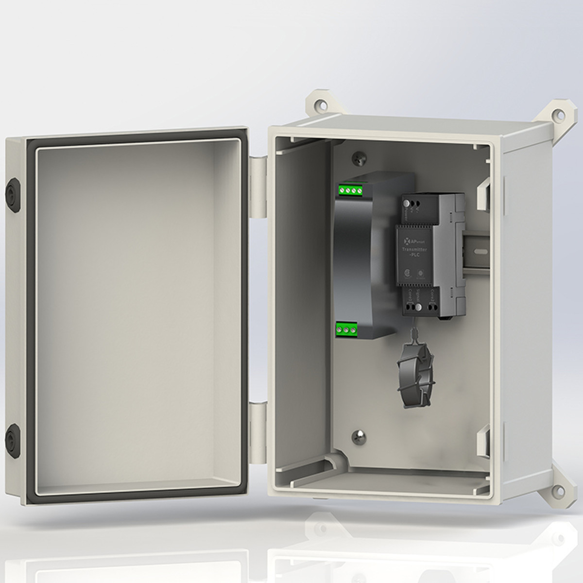
Transmitter should work since without it RSD would be in shutdown, and you may not have any transmitter in the system.

Do you have sufficient spare panels, RSD modules, and extra MPPT channel that you can use for bench testing if simply adding a transmitter does not work? Or own a truck/know locals into solar that can supply test components? I don’t have a truck but here near San Francisco I can craigslist or borrow via forums enough crap to achieve benchtesting in a few days. So no truck is literally the bottleneck.
 
i will look at options tonight after work. thanks for all the info.
i did see something like this, but i don't think that it will work with the 6000-TL
 
This sounds like a pinched wire, maybe take a string out at a time and kick the system on for each separately until you locate the bad string. Just had a SolArk with this issue. was causing the whole inverter to crash, just for one string. There ended up being a pinched wire and found it pretty quick under that string array.
 
i will look at options tonight after work. thanks for all the info.
i did see something like this, but i don't think that it will work with the 6000-TL
For this route:
  • You would need a string inverter that has a built-in transmitter
  • You would have to climb up and lift all panels to swap
Isn't it easier to unhook the MPPTs down at your inverter?!?

How many strings do you have? You will need to check the transmitter specs to make sure that the number of strings you have will fit inside the transmitter (it should be rated to hold X conductors). Probably single coil transmitter is enough.

With 8V out (assuming not phantom voltage) the RSD are probably in minimal output voltage mode for emergency power. How many strings in series, 8? If it is not phantom voltage, then probably the string is doing the right thing.

How did the installer not check this first? Hopefully it's because they said in the contract that troubleshooting is not included, and it's not primarily from poor training.
 
Yeah, I didn't think the JMS-F would work. Again, the 6000-TL isn't new enough or has the needed interface.
2 strings, they are wired to the SMA disconnect, 1 to each bank.
and i am not keen on changing out the RSD modules
that is what i keep asking myself. why the hell would you let that go. even if it's a CYA, we don't do that, or don't want to mess with that, just tell the person. don't gloss it over and let them get f'd down the road.
 
The JMS-F is also SunSpec like you APsmart. The protocol isn't some amazingly smart thing, it's just a keepalive signal modulated onto the wire.

Sorry to hear about your bad experience with the installer. I think if you get voltage on each string after buying the RSD transmitter, they are at least complete.

They should be willing to at least check connections if you can prove to them that the inverter is alive on one MPPT. Or you can call some other installer to do a service call for one panel ($$ though).

That said, it could be worse... there's zero chance in my area to get an installer that will touch customer provided hardware unless you know a guy who knows a guy.

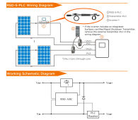
Here is how they are hooked in, it shows a two core model. It is just slightly harder than adding an energy monitor. Thankfully since you have the RSDs on the array the PV cables should be safe to manipulate, but of course turn off the physical DC disconnect first so there is 0V.

(confusingly the schematic is for the RSD and not the RSD + transmitter)

I don't see the number of conductors limit but I'm pretty sure 2 strings, of any sane AWG of PV or THHN, will fit. You can contact a retailer or APsmart to confirm I guess.

1689792332613.png

 
In the extremely unlikely situation that you replace the RSDs with something else, consider getting ones with panel level monitoring, that will help with debugging. Panel level monitoring in my experience is a big help when dealing with installers that have bad customer service because you can tell them exactly which ones are probably boned.
 
Back
Top