diy solar

diy solar

New no battery pure sine wave solar power system with smart switchers.

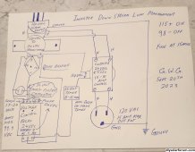
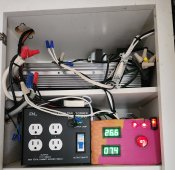
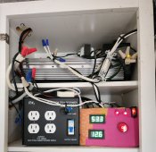
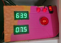
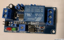
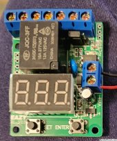
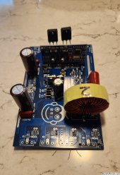
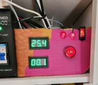
5 full days of system voltage controlled load management and system voltage power board crash protection.(One single $11 DC voltage controlled relay is handling this decision)

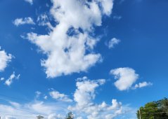
When compared to full sun detection method or letting the power board determine what it can and cannot handle in any given situation I have determined that the system is providing more hours of PV power in overcast conditions, Not just a little more but hours more at a time.

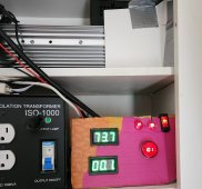
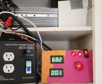
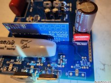
The relay protection simply will not allow the power board to crash and the secondary ISO makes for 550watts soft landing, Runs day after day without intervention and getting more mini split PV up time than ever before.?

I use to think it was all about full sun conditions, what I have learned is it is all about your volt+amps needs VS what the system can actually provide at any given time, this is a big step forward in real power production and day to day reliability.❤️

You should take another look at the project system with voltage controlled load management, should have tried this a long time ago.

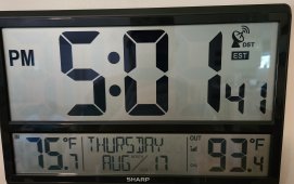
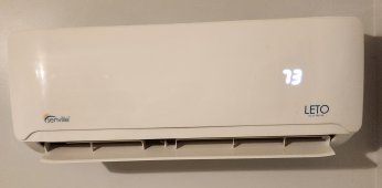
New favorite set point is 73 degrees Fahrenheit the AC runs more in overcast conditions.

This was an accidental discovery when the solar sensor was being worked on and lagging in operation,allowed a full day
of mostly PV operation of the mini-split in sub par overcast sky conditions.

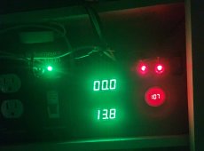
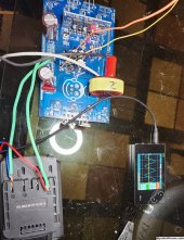
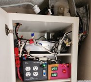
Love how the system waits till it gets the full sun power 115 system voltage before attempting to restore the larger loads.

Within 7 minutes or less of full sun conditions the largest loads return to the power board, taking advantage of every opportunity to run on solar ?

More later
 
Last edited:
What I am doing and why it works.

Have good quality grid power available that I am using to replace batteries in a PV solar power system, this approach works well 98% of time and is cost effective.

Should a rolling black out or grid down situation occur I have two solutions available first switch to PV solar only mode on the project system or start up a gas generator, Several other options are available to power/backup the secondary ISO in my home.

If you watch EV car news closely you will notice Hybrid cars are preferred over full electric because of the lower cost and improved reliability, The project system with grid support/boost allows much the same thing grid reliability and squeezes out every drop of solar day energy to reduce the cost of running lights,fans,electronics and Yes main air conditioning in several rooms. Mini-split and Quartz tube heaters from a 15Amp PV system.

The project power system with the recently discovered system voltage controlled relay load management is Awesome beyond words❤️

System protects itself 100% of the time, It exports day time solar energy to efficiently run loads and reduce your cost every solar day.?

5PM end of solar day photos, this power system performs great the home is cool and dry on a very hot/humid day.

No down time on the air conditioning with passing clouds sky conditions.

Last three photos: show low,medium, and maximum loading, zero on the bottom display is less than 1 amp draw from grid power.

Recipe that works for Hybrid PV power production:

From 5:30 PM to 9AM clock time relay controlled large loads to off or transfer the load directly to grid with a switcher unit.

From 9AM to 5:30 allow system to via the inverter voltage output controlled relay to control load management to the large loads to on(PV)/off or via a switcher unit to grid, 7-15 minute delay timers are needed to allow compressors to equalize for easy restart and to prevent the system from acting like a blinker.

This simple configuration may be applicable to other inverter systems and is providing 24/7 Hybrid support.

The 550 watts maximum after hours seamless power runs lights,fans, stick computers and Internet 24/7, Mini-Split and Mini-fridge are under system voltage load management, both use a 7 minutes delay switcher unit to dump directly to grid after hours or if not enough solar PV energy to run.

Best wishes
 

Attachments

  • 20230817_170142~2.jpg
    20230817_170142~2.jpg
    246.4 KB · Views: 8
  • 20230817_170222~2.jpg
    20230817_170222~2.jpg
    277.2 KB · Views: 7
  • 20230817_171518~2.jpg
    20230817_171518~2.jpg
    202 KB · Views: 7
  • 20230811_154600~3.jpg
    20230811_154600~3.jpg
    246.6 KB · Views: 7
  • 20230810_140619~2.jpg
    20230810_140619~2.jpg
    232.9 KB · Views: 8
  • 20230724_155239~3.jpg
    20230724_155239~3.jpg
    217.7 KB · Views: 8
Last edited:
  • Like
Reactions: Mil
14 consecutive days of full automatic system voltage controlled load management on the inverter, It really works?

Only adjustment that I am making daily is the Mini-split setpoint is raised to 73 degrees Fahrenheit for daytime operation and 71 for after hours.

Ton of information in the previous post.

My first draft of the switcher was a liner actuator that had switches at each end.

Dump to grid:
Green off(2 sec.delay)/(7minute adjustable delay)/grid on.
Green call:
Grid off(2 sec delay)/(7 minute adjustable delay)/Green on.

This is the correct sequence for a switcher, no chattering of contacts (arcing) allowed and delays mechanical and electrical must be included to allow any arcing to subside and avoid system surges at restart. I built four switchers three of them still working great.

Making the inverter system fully recover the system voltage to 115 volts before allowing large loads return to the power board is the genius part of the load management control. It works and the secondary ISO plus the relay set points is insurance on keeping the inverter happy ?

Best wishes
 
Last edited:
Today is a code orange Air alert day, along with the normal loads have add a ionic air purification unit with Hepa filter to the new power system.

12:15 PM 75 degrees Fahrenheit inside 92 outside very hot/humid and nasty conditions outside, project system continues to amaze ?

Just watched 3.7 amps load go from solar to grid and back solar during a passing cloud and the system never missed a beat in keeping everything running smoothly, When it returned to solar the grid useage dropped to near zero in amp draw ?

Watching the output voltage of any inverter drive power production system and making load management decisions based on this information is smart very smart!

Important: Using a voltage controlled relay to protect the inverter from overloads works very well, Proper soft start configuration and solid connection between the power board output and the ISO transformer to prevent system surges the results is a almost bullet proof power production system, Impressive durability, also the 40N65 MOSFETs are a hard to kill part in the first place.

Blue sky day is forecast for tomorrow ??

Best wishes
 
Last edited:
Perfect solar day ?

Rare night time picture of the 24/7 stuff normal after hours about 175 watts 1.38 amps on the secondary meter.

Lights,fans,Internet and stick computers with monitors, three security cams.

Room to spare on loads up to 550watts.

Second Picture less than one amp grid power and running large solar loads!
Third photo heavy loads on PV solar only secondary ISO is powered off.

Lot of things to like about the project system.

More later
 

Attachments

  • 20230823_212804~2.jpg
    20230823_212804~2.jpg
    228.4 KB · Views: 3
  • 20230701_161831~3.jpg
    20230701_161831~3.jpg
    281 KB · Views: 3
  • 20230725_114658~3.jpg
    20230725_114658~3.jpg
    278.1 KB · Views: 3
Last edited:
17 days and counting on the system voltage load management control $11 relay, It works perfect.

Only change I would like to make is a 15 minute delay timer on the mini-split instead of the 7 minute timer I currently have in use, Would limit the restart attempts to 4 per hour in heavy overcast sky conditions.

Works beyond expectations, setting the mini split set point higher will allow it to continue to operate in overcast conditions that you would think not possible.

A six day power outage in Michigan due to a tornado has prompted interest in my $4,000 DIY 15Amp solar power system, I highly recommend the project system.

More later
 
Here I go again parts ordered for next upgrade project: one $11 DC voltage controlled relay and one 12VDC up to one hour delay timer with relay $8.

Upgrading Mini-split switcher with independent load management based on green power voltage and a delay timer 15 to 30 minutes delay before returning to green power.

Could be used on any electronic power production inverter to manage loads, in my case the primary 180VDC PV input shifts the voltage past 115volts coming from the inverter and commands the additional loads to start, loads can run green as long as green system voltage is above 98VAC, if loads cannot be on green power they are transferred to secondary/grid or off.

You are welcome, I don't have the resources to patent the idea but everyone needs one of these super smart switching/transfer devices that runs solid state inverters daily for power production.

About a week to get the parts, excited to see this independent unit working magic from the project power system.?

Another Win-Win, Project power system and independent smart switcher for load management ?
 
Last edited:
Here you go simple block diagram of a million dollar idea for down stream load management off a green power inverter.

Concept is proven good 20 days of live testing.

115 VAC or above from the green inverter commands the extra loads to start (ON green call)

98 VAC and below dump or transfer the loads to secondary (OFF or secondary)

Independent,automatic, any where down stream of the green power inverter load management, no additional control wires to pull ✅

Definitely one of my best ideas to date load management and inverter protection in one independent unit that can be located anywhere on the green inverter power output system, It really works great on the mini-split.?

Don't forget 15Amp glass fuses for safety. Have been operating this with a 7 Minute delay timer successfully for the past 20 days, Right now it is in secondary mode for the night in the primary bedroom running the mini split at 71 degrees Fahrenheit, It works very well. More soon

Best wishes to all
 

Attachments

  • 20230831_202318~2.jpg
    20230831_202318~2.jpg
    593.2 KB · Views: 5
Last edited:
Blue sky day and a touch cooler outside, not only running the air conditioning and normal loads but also powering the rechargeable batteries for the lawn mower equipment.

Recipe that works, Mono crystal panels,40N65 MOSFETs,ISO transformers for the win.❤️

Parts starting to arrive for upgrading, Picture is the 1second to one hour delay timer.

New Version 3 of the voltage controlled relay in the second picture.
 

Attachments

  • 20230902_171240~2.jpg
    20230902_171240~2.jpg
    1.4 MB · Views: 4
  • 20230903_135125~2.jpg
    20230903_135125~2.jpg
    944 KB · Views: 4
Last edited:
Back in operation and ready for tomorrow with a 16 minute delay on the mini-split switcher, New Voltage controlled relay needs a 24VDC power supply that I don't have at the moment.

The voltage controlled relay will likely end up in a down stream load management device to disconnect quartz tube heaters this coming winter if system voltage drops below 98VAC and resetting to ON when it detects 115VAC or more, delay on break timers to keep from acting like a blinker.?

Love the downstream load management, pulling new wires in this 1941 home is a total pain.❤️

Another beautiful day, Fully automatic power system performs great.
 
Last edited:
Seriously if you are running solid state inverters daily for power production on a green power system track the system AC voltage daily and test loads.

You may discover a way to better manage a down stream load during peak production and make your system do more in my home Mini-split and Quartz tube heaters burn excess solar energy directly as long as the inverters are not suffering.

Not grid tie, Not like anything else it's better, No batteries, Low maintenance except for timer upgrade have not had to lift a finger in weeks, just keeps running and running.

Concept is proven good, Best wishes

HVAC 7 minutes delay on break timers are easier to work with with than the new timer just purchased, just went to the 16 minutes delay timer so less than 4 restart per hour in bad sun overcast conditions. So far working great.
 
Last edited:
How to use the new 1sec to 1hour timer board in a voltage controlled switcher system, Another mega cheat sheet looks simple but hell to make it actually work.

Making miracles happen with cheap off the shelf timers and voltage controlled relays, the past few drawings some of my best work show how to protect the inverter and manage large loads on a solar PV system.

Inverter is protected from voltage crash situations 24/7, loads are not allowed to return to green power inverter unless it recovers to full sun conditions 115VAC, timers allow for passing cloud conditions and load recovery.

It really is working well for me, timers $8, voltage controlled relay boards $11, Main power board under $100.

Simply bullet proof operation, also with DY002-2 CPU on the power board and 40N65 FETs auto recovery in seconds from most CPU error/trip events ?

Auto resumes loads on solar when sun conditions improve, amazing to see how it works.

More information soon
 

Attachments

  • 20230907_022424~2.jpg
    20230907_022424~2.jpg
    877.5 KB · Views: 6
Last edited:
Added single quick disconnect for all three solar arrays to the new system 15amps 27 panels, easy smooth operation to turn it all off instantly.

All timers and voltage controlled relays working beyond expectations, Grid backed system is reliable day to day.

Picture overcast sky conditions, Mini-Split still in operation although you wouldn't expect it to run, top meter is 20 amp full scale PV and lower meter is 10 amp full scale, preceeding zero on bottom display is less than one amp grid usage, Mini-Split is set to 74 degrees Fahrenheit.

The tiny additional grid power supports system voltage and provides MPPT full sun boost while PV pushes the lion share of the loads, Beyond cool to see it actually work.

A Hybrid cheat on a PV solar system that provides extra stability and functionality that is not expected, Unit runs great as a PV stand alone unit but with the secondary/grid boost you can run one third more in full sun and after hours you have 550watts of seamless 24/7 power availability for lights/internet/computers/fans and more.

System can be custom configured for more power but I absolutely love the ultra high efficiency of the 550watts seamless support Hybrid mode.
❤️
 

Attachments

  • 20230907_103340~2.jpg
    20230907_103340~2.jpg
    799.2 KB · Views: 4
Last edited:
Normal end of solar day is 5:30 PM but about 3:30 PM the clouds rolled in today and the system did exactly what it is supposed to do, all big loads shifted to grid and stayed there, the system recovered instantly but never achieved 115 VAC or more from PV solar to reactivate the extra loads the rest of this day now 8:00PM. At 5:30PM the system was already in night mode and ready for sun up tomorrow. Day after day of reliable power.

Basic concepts can be applied to other green energy systems, Let a computer protect the inverter and manage the loads 24/7 full automatic. Not hard to do once you start down this path, the project system voltage varies with the loads and a voltage controlled relay can make real-time decisions based on the numbers received (115 to 122VAC full sun and inverter ready to work/use) (98VAC and above OK to run all loads)(97VAC and below transfer loads to secondary or switch to off).
With the low maintenance of the project power system and 24/7 voltage controlled automation you will find many reasons to like this concept ❤️

More later
 
One month of Voltage controlled load management bliss off the 180VDC green power inverter 120VAC output,If I had known it would work this well it should have been tried long ago.

Stable operations since before May, It works very well exceeding expectations almost daily, Highly recommend project system with voltage controlled load management.✅


Best wishes
 
Last edited:
Off on a new adventure in building up a new 180 volt DC power board inverter, about 70% complete, missing one glass diode, all new parts except for the pure sine choke 3000 watt from another used power board.

What makes this board different using new EGS002 CPU instead of DY002-2 CPU (first time experimental), using super reliable 40N65 MOSFETs, jumping out fixed and adjustable resistors for Maximum power output, will use longer than normal jumper wires to the board so connections can be soldered end to end.

180VDC solar PV input 122VAC output very high quality pure sine power?

Wish me luck, More soon

Also building a voltage controlled relay to control quartz tube heaters down stream off the green inverter for this coming winter, dump to off if not enough sun PV power to run them, third photo raw items for load management DIY project ?
 

Attachments

  • 20230912_134744~2.jpg
    20230912_134744~2.jpg
    1.5 MB · Views: 4
  • 20230912_134702~2.jpg
    20230912_134702~2.jpg
    719.6 KB · Views: 4
  • 20230912_144847~2.jpg
    20230912_144847~2.jpg
    960.4 KB · Views: 4
Last edited:
End of day photo, 4 resistors and 6 pieces of wire before it can be tested properly, By tomorrow noon should know if it has a heart beat?

New CPU has the same pin out and jumpers, O scope and load testing will be reported on, have invested a work day so far in the build.

9:30PM finished all on board components, a few parts were harvested from used boards and tested before soldering to the new board.

Testing tomorrow.

Good sine wave and output on initial testing but CPU is flashing 3 times for over voltage although it is only being run at 20VDC, more work ahead to make the EGS002 CPU happy.

Early testing says I have a bad potentiometer 10K or connection ?
Feed back circuit for pin 15 is out of range, more soon.
 

Attachments

  • 20230912_201218~2.jpg
    20230912_201218~2.jpg
    825.1 KB · Views: 2
  • 20230913_101845~2.jpg
    20230913_101845~2.jpg
    1 MB · Views: 2
Last edited:
It works perfect in 3 second intervals, EGS002 CPU trips on (3 Flash) overvolt trip, must gain proper control of this function even if I have to order parts to do so.

Control circuit is isolated have high hopes to fix this issue. Also have second new EGS002 in the bag.

Going to find a project box and start building the independent voltage controlled load management device, Pictures to come.

Pretty sure running the 40N65 MOSFETs with the EGS002 CPU has never been done before, Normally the EGS002 is only used for a transformer system, Amazed it is working at all.

Going to learn something new here, may lead to another step forward. Beautiful sine wave and stability.

Tried several different things and no changes, did find test procedures for the EGS002 in a data sheet.

More soon
 
Last edited:
Finally some progress, After watching trouble shooting and testing videos on the EGS002 CPU.

Disconnected pin 15 (VFB) added 3VDC positive to pin15 and negative to powerboard ground to makes the power board run non stop perfect.❤️

Opening the circuit had no effect as well as grounding pin 15.

Slowly going to build up the inverter for a full power test, very happy right now ?

Inverter will be voltage protected/controlled externally as part of load management, EGS002 CPU has 3second auto recovery like the DY002-2 CPU, I will provide +3VDC from the +5 on the power board.

This is proceeding along easier than expected, have most of the parts needed to make another, Beautiful sine wave and 60 cycle power.

Have a nice circuit working to adjust voltage with a potentiometer and LED indicator, brightness indicates DC voltage was able to dial in exactly 3VDC.
Located +5 on the circuit board time to do a little soldering and testing. After the next batch of tests going to install the power board in a heat sink case for full power testing, will share the results with you.

2nd Combo unit will be back to 6,000 watts capable.

More details soon!
 

Attachments

  • 20230913_101845~3.jpg
    20230913_101845~3.jpg
    458.5 KB · Views: 2
Last edited:
New power board has passed all low voltage bench testing, Used 500K potentiometer and a white LED as a load and indicator.

+5 volts from the power board to the potentiometer to the LED and pin 15 (VFB) of the EGS002 CPU other side of the LED is connected to power board ground negative. Digital meter reading exactly 3VDC ?

Epoxy glued the potentiometer to the top of the 3,000 watt choke, Next comes full load and voltage testing. Going to add a third power board to the large inverter case for a 6,000 watt capable combo unit.

More information soon

Board mounted in case top and operational test, third picture is fit test perfect so far, tomorrow will be full voltage and load testing. Ready for tomorrow at 9:30 PM today, may take some time to see full sun conditions.

Later ?
 

Attachments

  • 20230916_034938~2.jpg
    20230916_034938~2.jpg
    1.2 MB · Views: 3
  • 20230916_160206~2.jpg
    20230916_160206~2.jpg
    1.7 MB · Views: 2
  • 20230916_161457~2.jpg
    20230916_161457~2.jpg
    1.7 MB · Views: 2
  • 20230916_160159~2.jpg
    20230916_160159~2.jpg
    1.4 MB · Views: 2
Last edited:
Reporting the good bad and ugly, everything looked great with the new experimental power board high voltage test 180VDC, was running the heater fan no problem but seconds after engaging the first quartz tube heating element the FETs shorted (At least two) no other damage noted CPU status lights burned steady afterwards.

Cannot recommended using the EGS002 CPU as a replacement for the DY002 or DY002-2 CPU, No damage done to the main project system life goes on?

Going to work on the down stream load management device next.Ordered 120VAC to 24VAC transformer for the needed power supplies AC and DC.

More information soon
 
Last edited:
Waiting on parts to arrive for the downstream load management device, Slightly cooler weather outside Mini-split is having no problems with keeping the home comfortable, Project power system exceeding expectations daily.


Have been very busy just starting autopsy on the experimental power board/inverter, have enough parts to do another 40N65 MOSFETs upgrade not sure I want to waste anymore parts right now on the experimental board.

Autopsy results, 2 bad FETs and one likely reason for the fault, small thermal resistor for fan start was taped down accidentally accross high DC voltage traces on the circuit board ? my bad.
Third picture.

More later
 

Attachments

  • 20230920_121019~2.jpg
    20230920_121019~2.jpg
    1.1 MB · Views: 7
  • 20230920_121007~2.jpg
    20230920_121007~2.jpg
    1 MB · Views: 7
  • 20230920_131521~2.jpg
    20230920_131521~2.jpg
    1.6 MB · Views: 8
Last edited:
Diagram of Inverter down stream load management off a green power inverter using the New Version(3) of the 24 volt DC voltage controlled relay.

This is what I will make,test and improve upon if necessary, Living room quartz tube heater will be controlled this winter by this automatic green power load management device, heaters will only start if adequate PV solar power is available.

It is not very complex, Looking forward to seeing it work.?

This load management device may work well with any green power inverter where the primary input causes the system voltage to increase 115VAC and above is on,98VAC and below off with a mandatory delay of eight to fifteen minutes. Have been using a similar device to manage a Mini-split this summer with great results.❤️


More soon
 

Attachments

  • 20230920_210515~2.jpg
    20230920_210515~2.jpg
    1 MB · Views: 7
Last edited:
120VAC to 24VAC Transformer has arrived HVAC part for all power supply functions 24VDC and 24VAC also provides sensor volts information for the voltage controlled relay, ordered 24VAC HVAC delay on make adjustmentable timer for the main contactor/relay.

More soon on the new build and Version 3 24VDC voltage controlled relay.

Contacts must switch only the 24VAC to the coil of the contactor/relay/timer.

Warning 24VDC voltage controlled relay can not handle 38VDC input apparently!

Obviously need to improve the 24VDC power supply before continuing, unfortunately replacement of the bad voltage controlled relay board is not in the budget right now, Will use the signal from a working 12VDC voltage controlled relay to control the down stream load (Quartz tube heater) the two wire control signal already exists about 10 feet away from where it is needed.

Delay timer due in tomorrow, should be testing in a couple days. Need a regulator for 24VDC on voltage controlled relay power input per the drawing gives 38VDC to the input of the relay board.

Must use output ISO transformer to use ground and earth ground per the diagram! ⚠️ 
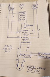
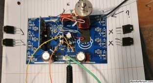
Power board must not be directly grounded to earth.

More soon
 

Attachments

  • 20230920_210515~2.jpg
    20230920_210515~2.jpg
    1 MB · Views: 4
Last edited:
120VAC transformer to 24VAC is working to power the 8 minute delay timer and 15Amp contactor/relay.

Waiting on a 5 volt DC pilot relay DPDT one side to trigger the 24VAC contactor coil/timer and second side run a indicator light.

Spent part of the day reconfiguring a two conductor wire from the oldest PV system 120VAC to a green neon indicator in the living room, Changing it to a 5volt DC switching signal from the new project system, has control over 3 switcher units and the quartz tube heater manager in the living room that is being built for the upcoming winter season. Also can control off and low on the secondary transformer or low/high on the ISO transformer. (Currently running secondary ISO 24/7 Factory normal for high performance 550watts seamless power)

Running the mini split this summer has gone better than expected off the voltage controlled switcher unit, had a good experience with the quartz tube heaters last winter but looking forward to living room heater voltage controlled management and second heater in the back hallway working off the same type switcher. Testing and part assembly have gone smooth today.

Green indicator light will be restored in the living room but it will show switcher status of the voltage controlled project system instead of grid power usage of the old system.

Much the same thing but the older system is delayed several minutes in the response to having battery backup delay the change over to secondary/grid when solar PV power is not enough.


More soon
 
Last edited:

diy solar

diy solar
Back
Top