diy solar

diy solar

New no battery pure sine wave solar power system with smart switchers.

Update on fuse testing:
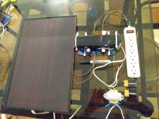
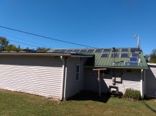
General protection for the 1000 watt pure sine power board 120 volt AC output in the 800 watt 9 panels configuration is 6amps 250 VAC fuse, on the PV array 5 amps 250volt max per each set of 9 panels but if you don't need max power 4 amp fuse make things more safe.
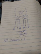
In the 2000 watt power board 1600 watt 18 panels configuration a 12amp 250 volt fuse on the pure sine power boards output will protect the FETs on the factory spec boards.
You can get more out of these power boards just attempting to set some safe limits.?
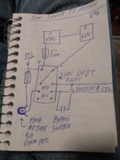
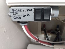
Recommend good quality DC switches rated for at least 200VDC!
180 VDC makes one heck of an arc especially when it coming off one end of your safety fuse ?
 
Last edited:
Sun sensor enhancements:
The sensor consist of two small 3 volt solar panels in series 6VDC and drives a DPDT 5VDC relay coil with a 51 ohm dropping resistor in line.
Working perfect for starting the system each day and putting it in a afternoon shadow that hits just before loss of sun on the array makes for a perfect end of day shutdown.
Problem is the 5 VDC relay latches just a bit to hard to respond to passing clouds properly, I have idea to use small resistive load 102 ohms across the coil and make it more responsive to passing clouds.?

Sun Sensor drawing updated to the latest version #4.
 

Attachments

  • IMG_20221019_200046307.jpg
    IMG_20221019_200046307.jpg
    116.8 KB · Views: 5
Last edited:
Looks like you should start your own Youtube channel then you can upload there and link from here.
 
Looks like you should start your own Youtube channel then you can upload there and link from here.
For reasons I will not go into I have removed all my videos from YouTube, I will be happy to give videos and pictures to anyone that wants to host this public information on this new concept for green power.
 
My short term plan is to double the FETs to (16) and retest car charging on the 2000 watt unit, If successful purchasing 9 more panels will become very important, no impact to the other solar systems car charging seems important nowadays.?
New power system is performing well even on a cloudy day.
A normal solar system inverter consist two thirds of boost FET circuits and transformers to get the DC hi voltage (180-380 VDC) needed to run the one third size output power board, by driving the output board directly from the PV panels you cut out the significant losses in the first set of FETs and even a larger loss in the small boost transformers, elimination of two thirds of the electronics and complexity of your average inverter is a good thing.?
Transformer belongs in final output section just before the output plug as an isolation (ISO) transformer and not wasted in a hi loss boost circuit.
 
Last edited:
After mapping out how the 2000 watt sine board FETs actually work in preparation to double them for car charging it has occurred to me that you could easily sync phase with another power system and do a seamless transfer with a solid state switcher, sync circuit will require isolation transformer and switcher will need the fault detector I came up with, a few small electronic mysteries to solve in actually driving the FETs but think it is worth trying as long as the cost is not too much.

Buddy just sent me an ad for a Alexa+phone driven app controlled 120 volt outlet. Add the fault detector and sync the green power and bam we have a whole new seamless way to do this.?
 
Last edited:
If you really want to avoid electronics charging your car, just get your panel Vmp up to the car's traction battery voltage and connect directly to it. No inverter required, no FETs, nothing but wire. (Of course, the tricky bit is convincing the BMS to turn on its contactors, but it can and has been done)
 
If you really want to avoid electronics charging your car, just get your panel Vmp up to the car's traction battery voltage and connect directly to it. No inverter required, no FETs, nothing but wire. (Of course, the tricky bit is convincing the BMS to turn on its contactors, but it can and has been done)
Think my KIA has a 600 volt battery to be honest 180VDC is as high as I ever want to go with this project keep it under 200 volts is one of my self imposed rules, also don't want to modify the car just to charge it.
Thanks for the input but it sounds dangerous / tricky.
 
I have decided to take a different approach to things due to recent events, parts I ordered won't arrive until November, Could use some help with properly making a transformer (120 VAC 60hz input to 5-16 VAC output) trigger the FETs in the power board to mimic the source 60hz signal in the output, This is the first step into making seamless transfers between different power systems and leapfrog the whole project into phone control/ Alexa control for your whole house. Thanks
The CPU does this with just 4 outputs on the pure sine board and the 1000 watt board produces pure sine power with just 4 FETs, Part number on the FETs is FGH40N60
I would like to do this properly the first time instead of hit and miss testing, Thank You!
This is my thoughts on how this might work dual output with center taps.
 

Attachments

  • IMG_20221013_064916198.jpg
    IMG_20221013_064916198.jpg
    96.8 KB · Views: 13
Last edited:
Powered up the CPU on the power board that has the FETs removed,I can see the 4volt pulsing DC triggering signal for each FET when referenced to the trace label gnd.
Seriously think before years end I will resolve all the remaining issues with making the switchers have seamless operation and fit into a robust home automation system that already exists.

Could use help from some young electronics guru, you can have the lead on this public domain project and see it over the finish line,need someone that likes the direct drive solar/smart switchers concept and a love for green power.?

Brain storm a moment ago imagine a device that can sync and seamlessly transfer to any one of maybe 5 different green sources of power.?
Just figured out the smart way would be to put the sync circuit in the switcher unit and not mess with the CPU protection and timing circuits of the power board, New name Smart Synchro Switcher ?
 
Last edited:
Thought experiment two sources of power worst case scenario 180 degrees out of phase how do you transfer the fastest way possible and not cause a fault??
Answer fast switches 1/30th of a second fast, drop the lead power at the zero point of the phase and turn on the second power source 1/30th of a second later. If anyone can muster this switch I can make it run safe, also needs to do the same thing in reverse.
 

Attachments

  • IMG_20221013_162216302.jpg
    IMG_20221013_162216302.jpg
    83.1 KB · Views: 3
Last edited:
Apparently not doing a good job of getting the message across, will put it in a nutshell so you can feel the excitement.
This small light weight system (Other battery system takes up serious amount of room in the back of the house) can provide 800watts of pure clean energy as long as the sun shines, the units CPU/fan can be powered by battery, transformer or small solar panel, running this unit directly from 9 solar panels across the top row in the photo provided is the most efficient solar power system I have ever seen. System pictured needs a metal case and fuses to be complete, with the addition of an isolation transformer it can run the whole house lights, fans and more daily, with the addition of a switcher if the lights are not running on solar they are on grid or your second choice of power.?
It is not magic but close, if you find this interesting tell someone else.

Also tested successfully 1600 watts on a 2000 watt board with 2 strings of 9 panels in parallel.

There is a 3000 watt pure sine power replacement board (never owned one) with three sets of 9 panels in parallel you could expect >2400 watts of pure sine power.?

I once owned a really nice Vertamax inverter the one third sized output power board failed when the wife was cooking with an electric skillet I replaced the single bad 3000 watt board with two of the 1000 pure sine power replacement boards and got two more years out of that inverter and boards ?
This was my first experience with the power boards and a good one although the two third sized boost section lower half of the unit went up in smoke both the power boards servived the one pictured here still runs perfect has a fan and ductwork to channel air through two small heat sinks, other one exploded due to my ISO transformer being stored in the shed.
All I am really doing here is using the PV panels at the magic 180 VDC to directly drive the output power boards, the surprise comes with how extrodenarly efficient things work without the booster FETs and multiple high loss boost transformers that are found in most inverters ?
 

Attachments

  • IMG_20221014_130930602.jpg
    IMG_20221014_130930602.jpg
    281.8 KB · Views: 18
  • IMG_20220928_142722060.jpg
    IMG_20220928_142722060.jpg
    255.8 KB · Views: 18
  • IMG_20221014_131012688.jpg
    IMG_20221014_131012688.jpg
    190.1 KB · Views: 18
Last edited:
Have the sun sensor tuned properly for passing clouds now?

Worked all day on this at one point the relay was working like a buzzer, found the correct way to use the resistors finally. The plastic hump on the sun sensor cast an afternoon shadow that forces a shut down just before the solar array has loss of sun around 6 PM est each day, with today's improvement for clouds detection may make this forced shadow not an issue anymore , todays shut down after 5PM was cloud cover not the shadow.
Updated drawing of the version 4 sun sensor.

Also working on a new idea to speed up the transfer by watching the inverter with a current sensor and complete the transfer the instant it can positively confirm the inverter is offline. Better yet use an independent powered logic unit to watch both power systems and control solid state relay switching.
Think I just solved the whole picture, now to make it work ?
 

Attachments

  • IMG_20220915_112817025.jpg
    IMG_20220915_112817025.jpg
    172.8 KB · Views: 6
  • IMG_20221019_200046307.jpg
    IMG_20221019_200046307.jpg
    116.8 KB · Views: 6
Last edited:
FYI bonus post : Here is a list of things you should not connect to your green power inverter systems, going to also suggest alternatives for each.

#1 Standard Vacuum cleaner/use LI-ION rechargeable instead see picture of my favorite.

#2 Table saw and circular saws/use rechargeable alternatives.

#3 Full size cooking appliances/It is not so much the load but thermostats and timers going on and off that seems to smoke the FETs, need a strong inverter to even consider cooking on green energy. Small cookers like a crockpot can prepare a hot meal.
Best to use gas for cooking.?

#4 Surge suppressor power strips normally have a second red led light on them/ Avoid them like the plague on green power systems and switcher systems. (Pure havoc and blown fuses) see picture.

#5 Starting motors/ although dangerous capacitors can assist in motor starting and large battery systems, on A/C and fridge compressors a normal 5-7 minutes delay is needed to balance the freon system and have an easy restart (normal 5 min on A/C units and small refrigerator about 7 mins) nothing much harder on an inverter than a stalled compressor motor.

#6 I would not recommend things that heats water like a dish washer or large motors or connect an arc welder unless you use special cycles or over sized industrial power inverters and such.

I recommend getting a strong good quality inverter or power board, cheap inverters rarely last a year.

For a solar newbie or off grid user this list could save you big time,I smoked many expensive inverters over the items mentioned above.?
 

Attachments

  • IMG_20221015_213753940.jpg
    IMG_20221015_213753940.jpg
    174.4 KB · Views: 6
  • IMG_20220921_103835034.jpg
    IMG_20220921_103835034.jpg
    198.7 KB · Views: 6
Last edited:
Solid overcast day but the lights stayed on nice and bright from 10AM to 5PM on direct drive solar, sun sensor is now working perfectly.
Just 9 standard Windy Nation 100 watt panels, a replacement pure sine power board and isolation transformer to drive the house lights circuit.?

With a sun sensor and switcher it becomes fully automatic, with a simple 15 amp double pole double throw switch you can test drive the whole experience, solar-off-grid switch.

Just ask questions if you don't understand something.
 

Attachments

  • IMG_20221016_120314701.jpg
    IMG_20221016_120314701.jpg
    94.1 KB · Views: 10
  • IMG_20221016_120411389.jpg
    IMG_20221016_120411389.jpg
    172.4 KB · Views: 10
  • IMG_20221016_120504238.jpg
    IMG_20221016_120504238.jpg
    188.5 KB · Views: 10
  • IMG_20221009_091900478.jpg
    IMG_20221009_091900478.jpg
    171.2 KB · Views: 8
Last edited:
Have been working daily on the sun sensor to improve it's function, now winter weather has moved in and noticably thicker clouds than previous days, sun sensor calling for grid power only.
As a test I reduced the lights down to about 200 watts and added a bypass switch for the sun sensor, surprise the lights are back on nice and bright, this new power system maintains 122-126 voltage even in very low light levels just don't expect too many watts running this way.?
 
faulted at 5PM (regular shutdown time) and I put the sun sensor switch back to normal, switcher went to grid, ready for the next day.
Simply amazing what can be done with these power boards.
Under heavy overcast sky, 5 LED bulbs,1 ceiling fan and 3 security cameras 10AM to 5PM.?
 
It is almost finished version 4 of the sun sensor will update drawing tomorrow just put in a nice bypass switch and 50 ohm adjustable volume control.?
 

Attachments

  • IMG_20221018_221324493.jpg
    IMG_20221018_221324493.jpg
    110.8 KB · Views: 5
I fail to see the reasoning for using a relay to detect solar energy when you have a micro.
 
Just simply easier to create a second independent control to experiment on, made a good sun sensor out stuff I had laying around, my vision is this entire concept in one case like a Panamax home theater power switcher and fully automatic, integrated with robust home automation systems that already exists, phone app and everything.

Need help with this public domain project, giving it away because of the just go and get a new electric car additude and that's going to solve everything, your average older home will never be able to charge even 1 car.
Not stopping until I successfully charge my KIA EV with the new power system, will keep working to package and automate the thing.

Car Charger worked for a full 10 seconds before 4 out 8 transistors (FETs) melted, I have a slow shipment of 20 FETs coming in November plan to double the FETs and try again with the 1600 watt system off a 2000 watt power board, wish me luck ?

New sun sensor takes it's place among the other active controls of my dual solar power system.
Currently my solar car charging uses grid power as a crutch, working hard to shift everything to the new power system.
 

Attachments

  • IMG_20221019_124058585.jpg
    IMG_20221019_124058585.jpg
    153.5 KB · Views: 11
Last edited:
Back
Top