diy solar

diy solar

New no battery pure sine wave solar power system with smart switchers.

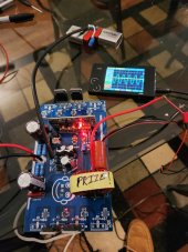
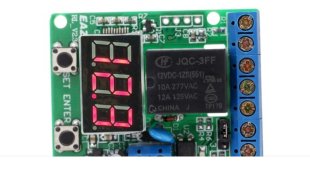
I use the DY002-2 factory CPU with 60Hz jumper modification and nothing else connected to a four FET 40N65 FETs board it has a perfect sinewave accross all load conditions and non stop run no matter what attitude. Generally a reset of the fault and restart of the CPU restores operation.

Glass fuse everything at 15amps or less (Recommended sizes) ISO transformers normally already have fuses, anything over 24volts belongs inside a metal case, be safe and do things correctly, capacitors charge and discharge warnings ⚠️
 
Can’t wait to test it out
On the way now. Excited for you this thing is a ton of fun just be careful.

Rereading all the pages looking for outdated and just plain wrong statements made during testing, some made statements that the system is basically useless because it has no energy storage capacity, I beg to differ when you are running main A/C summer, multiple quartz tube heaters in winter and the lights and more all the time, not much remains to be stored off the 18 or 27 panel solar system when used in this manner.

System is versatile, I am charging a green lawn mower batteries right now, no rule about using the energy the way you see fit

Congratulations!

More soon
 
Last edited:
Delivery date has cascaded by two days expect it Saturday before 9PM.?

Sun Sensor Version Five has developed an intermittent problem, fortunately it performed properly for weeks before this issue. Likely to rebuild the sun sensor on a circuit board with more indicators and test points, Thinking hard about a adjustable voltage controlled relay or just going full digital computer on the sensor control.

Still blown away that the 120VAC mini split can cool the 4 largest rooms in the home and maintain 72-75 degrees Fahrenheit with a 70 degree setpoint.

After starting the unit pulls 800watts or less, late afternoon heat and very cold nights push that limit on the heat pump, cold conditions can trigger a defrost cycle that may over load your secondary ISO.
For that reason I recommend quartz tube heaters in winter to avoid the defrost problem, Testing additional custom windings on the 15amps secondary ISO transformer may solve the defrost cycle overload issue.

Still a work in progress but what I already have working is amazing, A real dream come true.


More soon
 
Two missing in action, 7 tested good awaiting Z clips and installation.?

Nothing works as it should now days, at least not for me, spent all morning with KIA on 4 recalls the most bizarre responses from a dealership ever, giving me down the road for a two year old recall they refused to do the work because no one has a permit to work on EVs and KIA won't pay for the recall repair, KIA corporation insisted that I must use that dealership or I am not cooperating with their repair plan, the last recall notice says in plain English the high voltage battery can short out and burn the car. I kid you not.

Solar sensor working again, good solar day.

More soon

Upon closer examination the individual cell sections look amazing, I can smell the power?
 

Attachments

  • 20230609_125056~2.jpg
    20230609_125056~2.jpg
    367.8 KB · Views: 3
Last edited:
UPS has located the two missing solar panels and say I will have them Monday?

Z mounting clips have yet to be sent yet, can not make any forward progress without them☹️

Another wonderful solar day.
 
Helping the Prize inverter winner get started with a different set of solar panels.

Need 5 panels in series for 193 VDC to the inverter (Optimal 180VDC) just a little high but the second you start loading the system and doing real work this will vanish, you should get 1,350 watts from the 2,000 watt inverter (Not optimal but a good starting point,was stuck at 800watts for a long time) you need a 8.5 amp glass fuse on the PV (Combine 8amp fuse and parallel a one half amp fuse for 8.5 amps protection) if 9.03 amp short occurs the 8.5 amp protection will kill the feed.

The 40N65 MOSFETs running at only 1,350 watts will be bullet proof to hard useages,

The highest PV amp draw on the project system to date was 8.34 amps, you will like 8.5 amp availability ?

More soon
 

Attachments

  • 67A9FE43-F4EE-4A90-81E1-C40CF6D0E1A9.jpg
    67A9FE43-F4EE-4A90-81E1-C40CF6D0E1A9.jpg
    141.5 KB · Views: 4
Last edited:
If a second 5 panel array is added parallel 180VDC you could get 2,700 watts from 3,000 watt power board, I have a working example of a 4,000 8FET board based on the older FETs that could make use of the ten 270 watt panels.?

Everyone needs to look again, Talking about big power from a small direct drive powerboard, 1400 to 1900 watts for level one EV carcharging, 800 to 1000 watts to push the new 120VAC mini splits. The numbers look good ?

More soon
 
2,700 watt ten 270watt panels configuration to the 180VDC Inverter.

15Amp input and output fuses will keep the system running within the project limits.

Big power from a single small power board.
 

Attachments

  • 20230612_123552.jpg
    20230612_123552.jpg
    151.1 KB · Views: 6
  • 20230529_130713.jpg
    20230529_130713.jpg
    161.2 KB · Views: 6
I have all 9 of slim mono crystal 12VDC panels, tested and ready for installation, the panels arrived at least a week early and the Z mounting clips have yet to be sent. Just happy to get all 9 in new condition.

Once installed the project system will have the full 15Amp PV array, with the twin new FETs power boards using the power should be easy.

Prize inverter is headed for a big start with ten 270 watt panels, expect the full 2,000 watts from the inverter with room to start another power board.

More soon
 
Working on a new version of the sun sensor officially version #6.

Not in a rush.

Main focus is to eliminate the USB power adapter, secondly eliminate the pilot relay for transistor switched 12VDC that is headed for a relay anyway, increase the sensitivity.

This has to work better than previous versions or this is the last you will hear about it. Version 5 has become intermittent and I have yet to figure out why, If I can achieve the goals set out above it will be a win/win, Version 5 has proven multiple times that rolling clouds conditions can be handled expertly.

I really need the perfect solution this time.

Could seriously use help from others in perfecting the proven concepts of the project system, Phone app control Automation is the next big thing but I seriously don't have the resources to make it happen. Drawings of roll around cart of the power system could have network controls.

Still a work in progress but have seen all the pieces actually work and perform.

Build it like a gas generator but make it a project power system, people will buy and use it.

More soon
 
Last edited:
Just picked up the inverter! Can’t wait to start experimenting. I will take pictures of the unboxing!
 
Not pretty, that case at one time held two power boards side ways with heat sinks, May not be a Tesla first gen motor but represents all the baby steps in creating the power board project system. Boards have exploded inside that case during testing before I even had a clue about the ISO transformers.

Seriously have fun with it, I have another serious silver metal case to replace it with.

Congratulations

New power board, FETs, 3,000 watt pure sine choke and input diodes, custom tuned for high performance and efficient operations.?
 
Last edited:
Cheating on the solar sensor, Just ordered an $11 Digital DC sensor relay from Walmart. Fully in the spirit of the project cheap off the shelf parts to solve the problems 0.0 to 99.9 DC volt detection, more later on actual performance testing.

First is the one just ordered, second is the 7 year old charge manager for the old gopower system watches the deep cycle battery voltage and disconnects shore power when the batteries go high.

It will watch the 6VDC solar cell on the roof, will add a small load so the voltage varies depending upon the sun ?
Will control most aspects of the new ISO system and switchers.

More soon
 

Attachments

  • Screenshot_20230614_165123_Firefox~2.jpg
    Screenshot_20230614_165123_Firefox~2.jpg
    94.6 KB · Views: 4
  • 20230614_170359~2.jpg
    20230614_170359~2.jpg
    240.8 KB · Views: 1
Last edited:
All the (Z) clips have arrived for the 9 mono crystal solar panels.

Game on, I know what will be going on tonight and tomorrow.

Best looking clips to date.

More soon

7PM 95 degrees Fahrenheit outside hot/humid, temperature cool dry 76 degrees inside, lost PV sun support now 120 volt mini-split is on grid for the night, 10 hours of main solar AC today, 120VAC mini-split is amazing, project power system is amazing ?
 

Attachments

  • 20230615_185602~2.jpg
    20230615_185602~2.jpg
    209.1 KB · Views: 3
Last edited:
Just learned the correct procedure to use solder wick to open circuit board holes and remove multi pin components.
Requires high than normal temperature soldering iron,Flux and high grade copper solder wick.

Excellent YouTube video, old dog learning new tricks.?

Still attaching Z clips to solar panels.
Done 36 Z clips installed

Will start tomorrow installing the panels ?
 
Last edited:
All nine panels setting next to mounting screws, original layout would not have worked due to screws positions.

Waiting for 8PM to put at least 2 screws per panel before going to bed, will start the process of series connecting the panels.

Six in the lowest row, two on the end, one side ways on top that will be rotated 180 degrees and move some towards the camera.

More soon

9PM all nine panels have 3 screws each and all nine wired in series.
Two full days and the hard part is done about 8 hours of actual work, just need a good hot shower to finish the day.

Drill, bits and drivers, Silicone caulk and a box of 2 inch coated deck wood screws, Not so hard just find a row of roofing screws and reused one screw to attach each panel then drill and add more.
 

Attachments

  • Screenshot_20230617_175339_CloudEdge.jpg
    Screenshot_20230617_175339_CloudEdge.jpg
    684 KB · Views: 2
Last edited:
About one day to parallel the MC4 connectors for 180VDC, add a 5 amp fuse to the new string and upgraded the downstairs fuse to 10 amps, another 5 amp 9 panel feed gives the project system the full 15 Amp array.

Not working tomorrow but maybe Monday to get it completed, EV car charging by the numbers from previous attempts say full sun will easily charge the EV car and using the solar sensor the car will be disconnected until the next full sun event?
It will work perfectly have seen every part of it work but never had the full array for 100%PV and sun sensor automation.

Cannot wait to test the extra watts?
 
Last edited:
Really excited, the project system is about to be complete, running 10 amp secondary ISO input transformer, needs to be 15amps.

More important if you run the same loads 24/7 in my case big loads are shed to grid for after hours or loss of full sun conditions, lights,fans,monitors,computers and cams run 24/7 off the secondary ISO.

Building a wiring harness right now that will allow MC4 plug and play, will start tonight just before dark and turn on the new panels just before sun up tomorrow.

More soon
 
Can’t wait to see how this works for you
Have identified, exposed and tested roof top connection, awaiting sun down to make the final connections will be live for sun up tomorrow.

Will need a 10 amp fuse and must remove one turn from the PV current sensor.
Strange range 9.99 =20 amps, 7.50 =15 amps, 5.00 = 10 amps, 2.50 =5amps, 0=0, PV max will be 15Amps 7.5 on the top display.

Going out of town in a few days and will be gone a few days, Walmart DC voltage sensor will be tested as my main solar sensor upon my return, along with several other important test.

More soon
 
Last edited:
8:45 PM Done with full 15 amp solar array ready for sun up in the morning.

Three days and it is done, hope someone is taking notes:

2 days to build a power board.
3 days for 9 solar panels installation.
2 days wiring fuses,switches and testing ‐---------‐-----------
7 Days to a basic system.

More soon

Did something new that worked great, disconnect the last panel on each end of a series set for safety, last thing reconnect the two MC4 connectors at each end to activate the DC power.
 
Last edited:
New panels alive and well but unfortunately a rainy day in East Tennessee, testing will resume after a short trip out of state.

Unit will be left operational but no big loads this time around. Hottest part of summer yet to come and I look forward to stressing and testing the heck out of my additional watts of solar power.

Best wishes to all
 

diy solar

diy solar
Back
Top