diy solar

diy solar

New no battery pure sine wave solar power system with smart switchers.

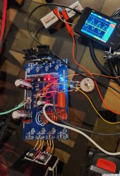
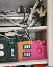
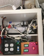
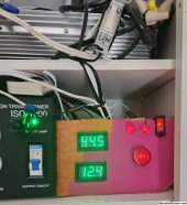
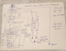
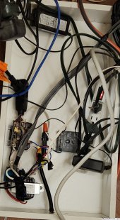
Live testing the Independent down stream load management device 120VAC 15Amp maximum, the top left voltage controlled relay is non functional and will be replaced with a 5VDC DPDT pilot relay powered by a 5VDC USB power adapter shown in green, trigger signal will be from another voltage controlled relay that has worked perfect for months.

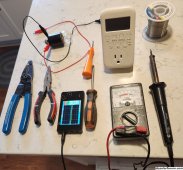
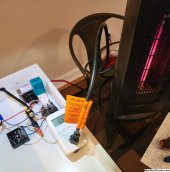
Just wanted to show you how easy to build this is, Automatic down stream load management from a green power inverter, only took a couple days to build ?

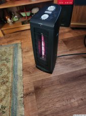
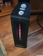
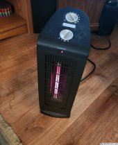
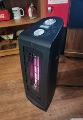
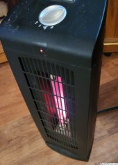
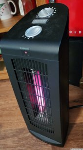
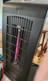
It is alive and will be running a green power only quartz tube heater in the living room area this coming winter.

Voltage controlled relay load management has changed the way I look at solar PV power, It is not about sky conditions as much as how much you can safely pull from the inverter at any given time.

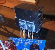
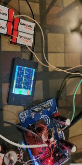
Drawing is correct but 24VDC needs to be corrected/regulated to voltage controlled relay input power specifications, it is important to use a little of the DC power to properly monitor the system voltage (a charged capacitor voltage will not change if some sort of load is not on the DC power feed), on the one and only working example a standard 25 watt light bulb is the load and is barely glowing the filament.

Please pay attention to what I am telling you, have been in commercial electronics all my life but only in the past two months have I mastered real time inverter protection and downstream load management off a green power inverter and it is all done with a cheap voltage controlled relay, In one basic step you protect the inverter and make a system so automatic you don't have to think about it ?
Seriously worth the effort.

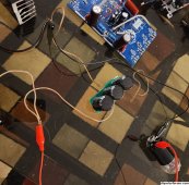
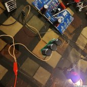
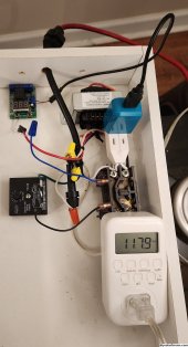
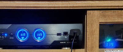
More soon with full power heater testing.Last photo 6.6 amps heater on high down stream more than 130 foot of wire 120VAC
.
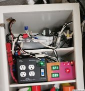
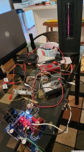
Main fuse is in the center of the load manager is 10amp fast blow glass fuse, maximum expected load from the heater is 7amps, system performs wonderfully, with reprogramming the voltage controlled relay set points or the system configuration you can customize the experience for your particular needs.❤️

Best wishes
 

Attachments

  • 20230925_114138~2.jpg
    20230925_114138~2.jpg
    490.2 KB · Views: 4
  • 20230920_210515~2.jpg
    20230920_210515~2.jpg
    1 MB · Views: 4
  • 20230925_161618~2.jpg
    20230925_161618~2.jpg
    902.5 KB · Views: 4
Last edited:
Everything works according to plan, with load management to quartz tube heater and displays in the living room.

5VDC pilot relay solved the problem ?

Highly recommended project power system and voltage controlled load management ?

Voltage controlled load management device cost under 100 dollars to build from start to finish 3days to build and have working. May work for any green power inverter that experiences a system voltage increase when the primary input is producing near full power.

Second Picture solar voltage numbers on the left and grid power usage on the right with switcher status.

Fun fact: Bright spots on heating elements picture is due to intense inferred heat overloading the Android phones camera, heat you can feel across the room, Will eventually attempt a repair on the experimental power board since I found an error in the build.

More later
 

Attachments

  • 20230926_094654~2.jpg
    20230926_094654~2.jpg
    537.2 KB · Views: 4
  • 20230926_054031~2.jpg
    20230926_054031~2.jpg
    1.2 MB · Views: 5
  • 20230926_052059~2.jpg
    20230926_052059~2.jpg
    578 KB · Views: 5
Last edited:
Flawless operation just wish I could afford solid state contactors for silent operation. (Recommended)

If you build one of these power systems the moment you pass the full load test on the power board inverter you will start smiling and years later you will still be smiling. Just walking out the back door most days and seeing the amp meters for solar and grid usage make me happy.

Not going to do the green check marks again but this project system is a very strong,reliable,efficient and stable collection of ideas for managing your electronic devices system comes in at $3,000 to $4,000 DIY and load management device comes in below $100 DIY. Nothing is very complex and YouTube videos exist for every subject.

Just need good soldering skills, you can increase skills by practicing on junk boards and wires. Component replacement and wire to wire or wire circuit board are the needed skills (Kit boards are fairly simple) CPU replacement is the hardest thing but I have managed 6 installs and 3 replacements successfully.

Best wishes
?
 
Last edited:
Experimental board with low voltage bench testing has a heart beat again ❤️

Replaced the two bad 40N65 MOSFETs with good used 40N60 FETs, also discovered the two 9 volts batteries I was using for CPU power were nearly dead, after 30 seconds of usage bad wave form and failed to start, this may have caused the failure in the first place (A good reason to insure proper power to the CPU)

Will slowly work up to 180VDC input test with full loads, more soon
 

Attachments

  • 20230929_133209~2.jpg
    20230929_133209~2.jpg
    619.2 KB · Views: 1
Last edited:
I've seen this symbol before on an inexpensive chinese inverter board.
It is a high frequency inverter and has very low surge capability.
It might run an ac but I doubt you could start one with it without it blowing after just a few starts.
China.jpg
 
I've seen this symbol before on an inexpensive chinese inverter board.
It is a high frequency inverter and has very low surge capability.
It might run an ac but I doubt you could start one with it without it blowing after just a few starts.
View attachment 170039
Inexpensive yes! The point is if you use 40N65 MOSFETs the unit is nearly indestructible in normal usages, Use voltage controlled protection and load management and it never trips the CPU trust me I have actually tried to kill the board and not succeed in months of doing so.

Seriously on to several somethings here contained in the project system that makes a world of difference beyond what you would expect in a low price build.

Can be run in many different configurations but my favorite Grid backed/boosted for 24/7 seamless operation is amazing, Hybrid operation of a PV solar power system has advantages you would not expect.

Secondary power can be from other sources than grid in my case a much older PV system with 4 large flooded batteries backs up up the core system.

BTW starting compressors is not the hard part running them late afternoon in 97 degrees Fahrenheit outside heat is the trick, 40N65 MOSFETs on proper heat sinks take the abuse day after day after day ❤️

Project is all about low cost common parts that do 15Amps worth of 120VAC power in full sun ?
Give it a try?
 
Last edited:
System Voltage controlled relays work better and is simply better than a solar sensor and it's roof top sensor and control wires/small solar cell.

Had good success with the solar full sun sensors but the voltage controlled relay is now project recommended.

Middle of page 22 through 32 have the needed information.
 
Have put a nice set of heat sinks on the experimental power board FETs, should allow for short term big load testing tomorrow. Have high hopes for success this time, found two solid reasons behind the fault.

If the board passes load testing I may upgrade the two 40N60 FETs to 40N65 and seriously upsize the heat sinks in a attempt for more amp flow.?
 
High voltage bench testing 120VAC to DC, on the experimental power board, It is doing real work but system voltage fluxes as I add additional loads, good but not good enough will keep testing and report if I find something interesting.

Main project system performs great daily, working through another partly cloudy day 84 out side Fahrenheit and 73.2 inside at 2:30 PM.

More later
 

Attachments

  • 20231001_140929~2.jpg
    20231001_140929~2.jpg
    691.9 KB · Views: 4
  • 20231001_140903~2.jpg
    20231001_140903~2.jpg
    643.8 KB · Views: 4
Normal 1,000/3,000 Watt pure sine board with an EGS002 CPU instead of a DY002-2 and 40N65 FETs, must supply 3VDC to pin 15 (VFB) to suppress 3 flash error. Would work good for stable loads like lighting or fans but not nearly as stable as the normal DY002 or DY002-2 and set of four of the 40N65 MOSFETs, magic recipe for the big win/ good heat sinks required?
 
First time running my KIA EV Soul all the way down to absolute 0 miles!

Interesting story have owned the car for 6 years and thought I had everything to handle the situation if it ever happened, KIAs new battery management software update was off the mark by a full 7 miles about 3 miles from home, managed a low power exit into a shell station off 411 Highway.

Called relative for ride home, picked up gas car and gas powered inverter generator 1,800 continuous watts, also the accessorie plugs factory and home made for car charging.

Because the generator only had one 120VAC outlet my adapters didn't work First time around, Long story short what worked was a 40 watt light bulb accross the netural and ground terminals of the outlet stripped off the insulation and stuck the wires into the outlet pushed in the charging plug and started the generator.

After about 30 minutes of charging the car made it home and back to normal charging.

If you look closely one of the three blue leds is lit confirming active charge from the generator.
 

Attachments

  • 20231004_134427~2.jpg
    20231004_134427~2.jpg
    975.5 KB · Views: 10
Last edited:
Building up a power board testing tool for quickly checking on the power board performances and output power.

The main drawing calls for 1,300 uf 250 volt filter/boost capacitor after the secondary ISO input transformer to power the inverter board, Testing earlier today says that a larger capacitor provides a more stable input/output voltage.

Testing an additional 1410uf 250volt past the boards own input capacitors with noticeably higher input/output voltage and rock solid stable operations.

In other words if you experience fluxes in voltage a larger capacitor will help.

⚠️Capacitors charge and discharge warnings for all 250 volt DC capacitors!

Tomorrow the experimental power board will be tested again,

Early morning testing of the large inverters two boards and the experimental board, Testing is not complete but seeing rock solid stable system voltage on the experimental board, 1,300uf filter/boost capacitor after the diode bridge is probably the minimum and should be doubled for more stable input and output voltages.

Stay tuned for the next improvement.

More soon
 
Last edited:
Could use help with a technical mystery that extends past six years solved the problem with the secondary ISO transformer.

When grounded neutral grid power is turned into DC through a diode bridge and filtered with a capacitor and sent to a FET drive power board everything works perfect (Glass table operation)

When blending 50/50 solar PV floating (non grounded DC power) and grid based DC power static charges build in the power board and diode bridge till a short occurs this arcing causes shorts that will cause real damage to the silicone based components.

Looking for another solution besides the ISO transformer, the bias is real and must be the reason PV DC power is isolated from earth ground/frame of the solar panels.

Here is a question what happens if the negative side of the solar PV is intentionally grounded and is blended with ground based DC from grid power??

Scared to try right now, maybe a test situation to limit the damage, anytime I have induced a direct ground connection to the power boards they short out and cause component damage.
 
Last edited:
Experimental board did 550watts for hours but the FETs (probably 2 shorted) when the load was increased to 850 watts, no clue what is going on interesting but probably will set the experiment aside for awhile and do something else ?

Normal project board can handle 2,000 watts or more, Best wishes
 
Have restored the experimental power board for the third time, soldered leads on two good used 40N65 MOSFETs and in less than one hour it is back working again. 4 - 40N65 MOSFETs EGS002 CPU.

Same two FETs went bad as before prompting me to test the FETs surrounding components, found nothing wrong with the support diodes and resistors.

Here is what the instructions say about dual inputs, the project system has no grounds on the DC inputs one guaranteed by the ISO input transformer and normal solar panels are isolated from earth ground on + and - leads from the panels.Also the doorbell transformer isolates the CPU/fan power.
Any thoughts?

Having fun experimenting and actually learning things, using a larger filter capacitor on the project system was a big step forward fixed more than one issue ?
 

Attachments

  • 20231007_195720~2.jpg
    20231007_195720~2.jpg
    837 KB · Views: 6
  • 20231007_200758~2.jpg
    20231007_200758~2.jpg
    1 MB · Views: 6
  • 20231007_201059~2.jpg
    20231007_201059~2.jpg
    1.3 MB · Views: 7
Last edited:
Got down to 40 degrees Fahrenheit last night, living room heater is running in automatic mode since 9:30 AM.

AWESOME

Low cost project system, Voltage controlled load management.

Also running overhead lights and fans,two stick computers,two monitors, three security cams, mini fridge, several rechargeable devices.?

Voltage controlled Heater can only run when solar input is high, About 200 watts running 24/7 out of 550watts seamless maximum, decision is made every 8 minutes to run or not, if heavy overcast or darkness exists no attempt is made to run the larger loads.

Voltage controlled relays are the best way to manage a solar PV system.?
 

Attachments

  • 20231008_102732.jpg
    20231008_102732.jpg
    835.9 KB · Views: 3
  • 20231008_104553~2.jpg
    20231008_104553~2.jpg
    812 KB · Views: 3
Last edited:
Here is what the instructions say about dual inputs, the project system has no grounds on the DC inputs
Many ??? As some smart people say to me,there is two ground one sort for lighting and another sort for AC or/and DC as you know,and they must not touch each one.

Iis it possible that problem is some V spikes and no grounds from PV and ISO input? How about classic light ball 40W between ground and DC -,and/or AC?
To remember my limited know I don't get why is synchronise important but belive it is. If DC 16V is suplay how it can be synchronized?

Can PB work only on PV suplay w/o AC at all?
Best
Never thought about a load accross the different inputs. Hmmm

Right now in the middle of testing Grid to diode bridge to big filter capacitors to Power Board. Should be able to run heavy loads, But as with past testing any attempt to hook a grounded neutral from grid power directly to the board causes Fets short problems and general instability in operation.

The triple ISO transformers input,output and doorbell transformer for the CPU is the secret to rock solid operation and safety of the project system.

The only way I found to sync all three successfully has been the isolation transformers. Actually the PV panels are also by design isolated from earth ground.

3:30 PM on overcast sky afternoon, single tube still running on the quartz tube heater.

Most amazing thing I have ever seen, Pictures. System voltage is 107 VAC the heater will run as long as the system voltage stays above 98VAC. Top meter 20 amp full scale, Bottom meter 10 amp full scale.

Natural power blender is keeping grid usage to a minimum preceeding zero on bottom display is less than one amp of grid usage.
?
 

Attachments

  • 20231009_153202~2.jpg
    20231009_153202~2.jpg
    812.4 KB · Views: 4
  • 20231009_153144~2.jpg
    20231009_153144~2.jpg
    934.8 KB · Views: 4
  • 20231009_153233~2.jpg
    20231009_153233~2.jpg
    797.9 KB · Views: 4
Last edited:
Voltage controlled relay for green quartz tube heater has worked for 3 days now in Automatic mode, currently running heater on one heating element successfully in overcast sky conditions.

Only suggestion is for a solid state contactor/relay for silent operation.

Have crossed another finish line in automatic operations. One system voltage controlled relay and one timer 9:30 AM to 5:30PM daily schedule. It really works with secondary/grid support to replace batteries in a solar PV Hybrid system.

System voltage controlled relay commands 3 Green-off-Grid switchers,1 Green only heater, and a currently not in use High 830watts/Low 550watts normal mode, have been running normal factory 550watts mode for months now on the secondary ISO transformer.?

Seriously efficient in power blending and PV production 24/7 seamless 500 watts comes in handy for lots of stuff. Backup of the secondary ISO transformer makes for something special.
 
Last edited:
See I have been relocated?

Everything still working great with the project system, Recent testing has confirmed earlier results.

A power board running 40N65 MOSFETs and isolated from earth ground makes for a great solar green power inverter.

More later

Load management quartz tube heater also doing exactly what it is supposed to.? on a cold overcast sky day.
 

Attachments

  • 20231016_140717~2.jpg
    20231016_140717~2.jpg
    797.7 KB · Views: 2
  • 20231016_140801~2.jpg
    20231016_140801~2.jpg
    803.8 KB · Views: 2
Last edited:
Safety Post:

Use safe 12-18 VDC battery power to build/repair and initially test the power board units!

Anything above 24 volts belongs in a metal case and needs appropriate fuse or breaker protection. I broke this rule with the load management device and will put it into a suitable case soon, Unit has a 10 amp fast blow glass fuse for protection.
Just wanted to show you a functional unit before stuffing it into a box.
Voltage controlled load management is working awesome.?

PPE use eye protection always and rubber gloves if not sure about working with 180VDC !

Once high voltage is applied to the power board unit through solar panels or secondary ISO transformer you must assume the capacitors are charged Working or Not⚠️

My method of dealing with this is to use a 25 to 40 watt standard appliance light bulb to discharge the capacitors after disconnecting all power board inputs solar/secondary/grid ISO transformer!, See pictures: Putting the bulb across high DC voltage input to the power board will drain in seconds.
Second Picture is actual draining the three capacitors, note the capacitors on the junk power board, 25 watt bulb is barely glowing indicator the capacitors are almost discharged normally takes 3 to 5 seconds (If the bulb stays on warning one of the inputs is still on!)

Use proper tools, as a last step place a jumper wire accross all inputs. Terminal strips are preferable over wire nuts, Just starting my retirement will rework everything including the card board display, The Mosfets the unit is based on act like a big smokey fuses if seriously abused they will fail and open the circuit. Actually smoking the FETs/board has become a rare thing since introducing the ISO transformers in all testing cases the FETs faulted for example: Grid VS Inverter FETs fail,Full system surge FETs fail,Lightning direct strike FETs fail, before 40N65 FETs voltage crash the FETs fail.
By using input and output fuses,ISO transformers and the nature of the FETs make this project as safe as can be for a power production unit.

Intrinsically safe by design, the fuses,ISO transformers,FETs and circuit board traces all work to safely limit the energy discharge in a worst case scenario, Dual DC inputs makes it physically impossible to backfeed the secondary ISO AC power system, System is tuff as nails, have power boards older than 6 years still working ?
Seriously easy to upgrade Mosfets or repair if needed last 40N65 MOSFETs upgrade took about an hour, building a 2,000 watt kit board is not that hard and a easy way to get the correct FETs.

Be safe three or more solar panels in sunlight can kill you, 120-180 volts Mains and capacitors charge and discharge warnings must be observed, unit must be fused at 15amps or less.

Although it is still Mains voltages I am proud to have kept everything under 200 volts on the project power system.

System performs beyond expectations if built correctly. ?

Best wishes
 

Attachments

  • 20231017_101826~2.jpg
    20231017_101826~2.jpg
    1.1 MB · Views: 5
  • 20231017_100449~2.jpg
    20231017_100449~2.jpg
    1.1 MB · Views: 5
  • 20231017_100444~2.jpg
    20231017_100444~2.jpg
    1.1 MB · Views: 5
Last edited:
Finally got some sun, Heater on Hi now everything is ON ! ?

Voltage controlled load management is working perfect. 22 consecutive days of perfect operation !

Bottom display 10 amp full scale top meter solar 20amp full scale.

Secondary ISO transformer on the new system is fully backed up by another much older solar/battery system that has about 4 hours of run time, Bridged two rolling black outs last winter no problem, have already passed the test to do it again this winter.
During last grid down test noticed wife's laptop was not charging now it is on the new power system.?

How many realize my grid usage during daytime on the new project power system is actually solar green power as well, please ask questions if you need assistance with anything ?

This dimond in the ruff power system makes for an excellent platform for demanding electronics.

Maintaining 107VAC system volts,
only 1.24 amps grid useage, 50 degrees Fahrenheit outside ❤️
 

Attachments

  • 20231018_112839~2.jpg
    20231018_112839~2.jpg
    942.2 KB · Views: 2
  • 20231018_112910~2.jpg
    20231018_112910~2.jpg
    738.5 KB · Views: 2
Last edited:
EV car is expensive and falls short of written expectations.

The technology needs better batteries before I recommend you put your hard earned money in one, yes fun to drive but my last calculation says I am paying in excess of $20 per mile for the experience.

Check out my 11 year old poker game on Roku streaming player, GridWorks Software - Double Draw Solo Poker.

Other GridWorks projects : Tail Gate rig for DTV HD over 69,000 views last check, Omni-Com BBS communications in the 1980s, this project approach to green power is far more important than anything I have done previously and do not understand why more people are not interested, The cost of energy just keeps rising.

Low cost common electric parts, proven real world full load testing, years of good ideas rolled into one power board system, DIY approach can save you big.

Caricature of me in the middle.?

Best wishes
 

Attachments

  • 20231019_164604~2.jpg
    20231019_164604~2.jpg
    2 MB · Views: 2
  • 20231019_164436~2.jpg
    20231019_164436~2.jpg
    694.1 KB · Views: 2
Last edited:
Just ordered two more of the 2,000 watt kit boards mainly for the CPUs,Main circuit boards.and pure sine chokes.

Getting harder to find on Ebay and I seriously want to future proof the project system and help others if needed.

Total was $100.68 for two of them, in case they don't ship with the 40N65 MOSFETs I still have a new set of four ready. Fun fact: last kit board ordered about one year ago contained the first set of 40N65 MOSFETs that really changed everything a really hard to damage part. Reset normally restores power board after any fault condition DY002-2 CPU will automatically attempt restore in a few seconds from simple overloads.

Too thrifty of a person to keep purchasing the same thing for 6 years if it was not superior in performance, The secret is to isolate the two sided power circuit board from earth ground with ISO transformers and use 40N65 MOSFETs with large heat sinks and a small vent fan.

40N65 FETs Push motors very well, Quartz tube heaters and 120VAC Mini-split perform good, only real problem is the defrost cycle for heat on the mini-split in low temperatures, Main reason for Quartz tube heaters in winter to avoid the defrost problem.

Takes direct 180VDC from the solar panels and turns it into gold standard 122VAC 60Hz power for your electronics.

Voltage controlled load management is a blessing/icing on the cake.?

Heater pulls just under 7amps on high, All the 24/7 stuff 2 amps Main system running just under 10amps with 15amp maximum capacity.?
 

Attachments

  • 20231021_104427~2.jpg
    20231021_104427~2.jpg
    692.2 KB · Views: 1
Last edited:
Watched excellent video on driving MOSFETs, went over my head quickly but he demonstrated touching the gate with his finger triggering the FET to ON.

The hum of earth ground makes the FETs switch on early/late causing unstable timing and shorts in opposing sets of FETs.

My task is to divorce DC power from earth ground with other than an ISO transformer and produce ground isolated DC power just like the solar panels do already for the power board.

Solving this one technical mystery could make this project much less expensive and easier to build.❤️

Project system would still need the output ISO transformer for proper ground/neutral and board isolation.

Best wishes
 
Last edited:

diy solar

diy solar
Back
Top