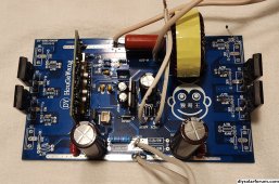
diy solar

diy solar

New no battery pure sine wave solar power system with smart switchers.

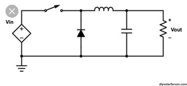
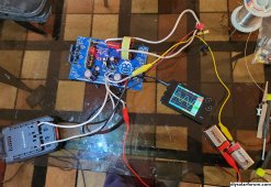
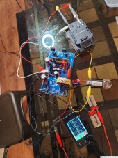
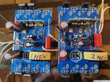
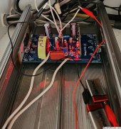
Interesting design for an Isolated DC to DC converter.

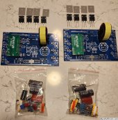
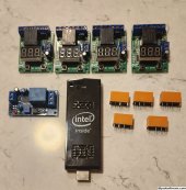
Pretty sure I already own the parts needed especially to just bench test one.

Wish me luck, Concerned it won't work due to the direct ground connection on the bottom of the diagram, we shall soon see.

Power Board in the early days said a big NO to negative grounded DC power.

More later

Found nice clamp on amp meter that has been missing for three years, batteries had leaked and corroded but easy clean up with removable tray, nice to have it back again ?
 

Attachments

  • Screenshot_20231022_121100_Firefox~2.jpg
    Screenshot_20231022_121100_Firefox~2.jpg
    52.4 KB · Views: 6
Last edited:
1,400 Sq ft home built in the 40s, East Tennessee four season weather, Daytime solar production around 3,000 watts across two systems/ night time is grid only support making this a Hybrid PV no battery solar system.

Hope to get a $40 utility bill actually came in at $70, Keeping the primary bedroom just a bit warmer this year at night, House stays comfortable 24/7 main four rooms, two ceiling fans and one additional stand fan winter only redirect warm mini-split air into the main living area.
120volt Mini-split in primary bedroom on new power system and a 220Volt Mini-split in the hallway on grid for main winter heating needs, new system drive quartz tube heaters in the living room and back of the home provide heat even on a overcast sky condition day.

Little buddy gas heat and 1960 gas stove if the crap hits the fan.

Look at May,June,July,August mostly green solar power the four largest rooms air conditioning off 120VAC Mini-split very hot summer in the 90 degrees Fahrenheit range, indoor Temps in the lower 70s degree range with low humidity during the day.?

Real success in reducing the cost to air condition the home, most of my neighbors get a two or three hundred dollar utility bill.

More soon
 

Attachments

  • 20231023_193645~3.jpg
    20231023_193645~3.jpg
    284.2 KB · Views: 2
  • 20231023_193322~2.jpg
    20231023_193322~2.jpg
    759 KB · Views: 2
Last edited:
Ordered two more of the $11 voltage controlled relays 12VDC version 99.9 VDC sensor.

Considered essential for Inverter protection and load management now, computer real-time control and protection in one simple package.

Thirty days of full automatic on the voltage controlled load management and project power system continues to amaze.

More information in the utility bill post.

It really works great.?
 
Last edited:
Neighbor a few houses down the road met with me in the driveway to discuss my solar installation, told him $3,000 to $4000 DIY for the new system and gave him a look inside at the inverter setup, also explained $70 utility bill no maintenance and no batteries approach.

Would like him to return on a sunny day for more information, pointed him to this thread for more information on his phone.

Even on a seriously overcast sky 30% to 40% of solar is running the heat and lights in the home.

Forecast much colder weather and mostly sunny days ?

Best wishes
 
Last edited:
Everything continues to work day after day, Right now running quartz tube heater on High in the living room recovering from an outdoor temperature of 22 degrees Fahrenheit last night at 1:15PM indoor temp is a 63 degrees and increasing.

From the single project system the heating is supplemental in really cold weather but with Mini-split air conditioning in the summer time the largest 4 rooms stayed comfortable mostly on green solar power.?

Got it right the first time on the project system, ISO transformers are superior in many ways.

Full DC protection and isolation from the solar panels,fuse/breaker safety as well.

Output ISO performs miracles in correcting the AC output to run the most demanding electronics and push motors well.❤️

Isolation transformers are temperature protected on the primary winding.

Triple ISO transformers provide a superior environment for stable power production on the FET driven power boards.

ISO transformers are naturally energy efficient and have extremely long life expectations in normal usages.

Around January I will build a solid state input for secondary power input just to prove that I understand how to make it work properly, just use the appropriate ISO transformers for a safe and productive system.

More later

Safety first use rated devices/wire to build the project system some diagrams shows power strips, using romex and rated outlets to do the same thing is encouraged way of thinking also using terminal strips instead of wire nuts is recommended.

Now that everything works according to plan I will soon eliminate the wire nuts with terminal strips and go with a metal box for the displays.

Best wishes
 
Last edited:
Ebay order has arrived ?

Two new 2,000 watt Kit boards.

Exactly what I wanted, New very nice MOSFETS 40N65, Automatic CPUs DY002-2, Full sine chokes are high quality parts, circuit boards are also excellent.

$100 for the two of them.

Add solar panels, case with fan, two ISO transformers and a doorbell transformer for the main system.

Other parts fuses/holders, relays/voltage controlled,filter/boost capacitors, diode bridge and terminal strips.

Ask questions if you need help with anything, small power board with robust pure sine output.

Super Hybrid power production and operation on two different levels synced with the ISO transformers.

Not kidding you operation of this unit with the secondary Hybrid boost input as a platform voltage increase makes a real difference in PV power production and stability across variable loads and sky conditions. Using a system voltage controlled relay to dump or transfer loads protect the green power inverter from a voltage crash in real time.

Operation of the power board in the triple ISO transformer environment with the 40N65 FETs makes for one heck of a stable platform for your demanding electronics.?

More soon, not like the others direct drive solar, no charge controller,no batteries very low maintenance and with DIY approach can save you big.

Have been working on this for about 6 years, mega improvements since December of last year many real world tested improvements all rolled into one project power system.
 

Attachments

  • 20231102_184754~2.jpg
    20231102_184754~2.jpg
    1.3 MB · Views: 6
Last edited:
Took just a little over two hours to build one of the kits.

Ta-Da beautiful sine wave just need to change the jumpers on the CPU for 60Hz power.

Important information use only one of the large input resistors on the feed back to the CPU trace, use a single wire to bypass the other resistors for DC power input any other location will do, I bypassed this board with a short jumper on the backside traces. Also turn up the potentiometer full clockwise about 30 turns (Max power) configuration.

Some make a slight click noise on maximum clockwise.

Don't mix up the two 5volt and 12volt voltage regulators looks the same double check part numbers.❤️

Sharp point soldering iron for CPU installation and voltage regulators, practice first on resistors and other small parts.

Reference this picture or operational board when building the kit DC round capacitors have a direction and won't function correctly if reversed!

Best wishes

Passed bench testing for export to the inverter case AWESOME!
 

Attachments

  • 20231104_165435~2.jpg
    20231104_165435~2.jpg
    1.8 MB · Views: 6
  • 20231104_203643~2.jpg
    20231104_203643~2.jpg
    1.7 MB · Views: 6
Last edited:
Recent changes that have made the power project easier to build and enjoy.

Only modification needed on the secondary ISO transformer is a rated diode bridge mounted in the bottom of the case to feed DC to the power board, no extra secondary windings needed unless you need more 24/7 power than 550watts factory mode. This mode is recommended for maximum efficiency with power blending solar and secondary power ISO input.

System Voltage controlled relay is simpler to build and far more responsive than the rooftop full sun sensor, Now project recommended works in a dual roll as green inverter protection and load management trigger signal.

System is fully automatic and will take care of itself, but real world example of common sense adjustment in extra loading the system on a clear sky conditions day heater/AC on high, hazey overcast day heat/AC on low, rain/snow day switch heat and air to off till conditions improved, with secondary support the 24/7 stuff will run non stop.

Even if you get it wrong the voltage controlled relay has your back and will stay off till the system fully recovers.

Amazing how well this operates at the end of the day everything is ready to do it again tomorrow.

More soon

Starting a very special build on the second power board kit, likely never done before this way should provide better heat transfer from the FETs and shorter path for the DC power to input to the FETs, Idea occurred to me while studying the circuit board traces.
 
Last edited:
Two for two in a row ?

This one is special notice the spacing of the FETs for better heat distribution also closest possible distance on the DC inputs (shorter distance to beef up traces for more amps)

Still building it but perfect sine wave 60Hz power, test load is glowing ✨

More soon
 

Attachments

  • 20231106_131211.jpg
    20231106_131211.jpg
    961.8 KB · Views: 8
  • 20231106_152700~2.jpg
    20231106_152700~2.jpg
    1.8 MB · Views: 8
Last edited:
Hi,just find this,
View attachment 176435
any useful apply without your great work?
Neutral and - in one spot?
Does this can without ISO?
Instead of battery just 2PV of about 200 DC each and go,but of corse without AC for about 3KW.
What about connect ground from PV and AC output?
Just to eliminate NTC and SSR for heater.
https://www.homemade-circuits.com/5kva-transformerless-inverter-circuit/ more:
Love the circuit you could have two solar arrays for B1 & B2 the part I don't like is the earth ground between B1 & B2 need to study it more, Thanks

Another step forward with the latest kit board build, promise of more amps and better heat distribution off the MOSFETS ?

Best wishes
 
Both new kit units working perfectly, definitely got my monies worth on the 2,000 watt kits.

Still have 4 new 40N65 FETs and a six years old factory board that can be upgraded if needed.

Last kit will be built up for maximum performance and tested hard?

Picture of maximum full sun PV production 75.0 would be full 15Amps, preceeding zero on bottom display is less than one amp (actual .62 amps grid usage), top meter 20amp full scale and bottom meter 10amp full scale.


More soon

With multiple voltage controlled relays you can customize load management to sky conditions perfectly.

Future proofing the project power system, Voltage controlled relays and timer have arrived, ready for what comes next.❤️
 

Attachments

  • 20230402_105228~2.jpg
    20230402_105228~2.jpg
    1.2 MB · Views: 2
  • 20231106_192459~2.jpg
    20231106_192459~2.jpg
    1.7 MB · Views: 2
Last edited:
Board #1 has been set to 60Hz output.

Board #1 has been completely resoldered for maximum amp flow also the power traces beefed up for maximum DC input amp flow.

Board #1 is destined to be a strong inverter soon?

Board #2 is currently non operational due to a accident in testing the 5volt and 12volt regulators, suspect blown 5 volt regulator, and possibly the CPU took a hit, lost control of a test probe on the CPU buss checking voltages.
Absolutely stunned this happened to that particular power board.

Board #2 has new 5volt and 12volt regulators, CPU still no go ☹️

More later

Board #1 headed to inverter case installation.

Board #2 will be prepared for CPU replacement needs DY002-2 part, Have EGS002 new in the bag online says they are the same but real world testing says a big NO with full loads the FETs will short out in opposing pairs.

More later
 
Last edited:
Fets correctly mounted to inverter case, unit still running smooth, ready for high voltage test.

It has only been a few days since the kits were delivered about to connect 15 amps of 180VDC green PV solar power to the board and put it to work big time.?

Not that hard.

I use sheets of card board underneath the board with 1/3" lip up behind the FETs for positive spacing, ISO pads behind the fets for heat transfer.

Test load glowing exactly 60Hz on the "O" scope everything looks great to proceed.

More soon?
 

Attachments

  • 20231107_201246~2.jpg
    20231107_201246~2.jpg
    888.9 KB · Views: 4
Last edited:
Unit passed all High voltage test ✨

Unit will run for the next 5 or 6 years maybe much more depending on the new 40N65 MOSFETs, hard to kill part that really delivers on output.?

Ta-Da easy magic, close as most will ever get to real magic 100% solar 15Amps 180VDC input, Output 122VAC pure sine goodness.❤️

Not that complicated or costly when you focus on the details. Six days from mail box to running a heater and light bulb,

More soon

Final assembly remains ?
 

Attachments

  • 20231108_130936~2.jpg
    20231108_130936~2.jpg
    742 KB · Views: 5
  • 20231108_130924~4.jpg
    20231108_130924~4.jpg
    1.1 MB · Views: 5
Last edited:
Board fits perfectly inside top half of inverter case, This case contains 3 of the premium 40N65 FET boards 6,000 watt combo unit with thermal fan control.

All tested and passed loading.

Currently the project system has 27 standard 12VDC solar panels and two of the premium power boards. This may in time replace the main inverter.?

Recommendation for mono crystal solar panels. Better power curve and durability.

More later on
 

Attachments

  • 20231108_193722~2.jpg
    20231108_193722~2.jpg
    1.1 MB · Views: 1
  • 20231108_193736~2.jpg
    20231108_193736~2.jpg
    714.6 KB · Views: 1
Last edited:
Hi,just find this,
View attachment 176435
any useful apply without your great work?
Neutral and - in one spot?
Does this can without ISO?
Instead of battery just 2PV of about 200 DC each and go,but of corse without AC for about 3KW.
What about connect ground from PV and AC output?
Just to eliminate NTC and SSR for heater.
https://www.homemade-circuits.com/5kva-transformerless-inverter-circuit/ more:
You may be on to something with that circuit, do you have the resources to build that ?

My interest would be to adjust B1 & B2 for perfect 120VAC and check for proper pure sine output.

If the 2 FETs version works the same or better than the 4 FETs currently in use I am on board with it, testing it without an ISO transformer will be interesting as mine would fail if connected in that manner.

Thanks , Like I said you may be on to something if it is real world tested.

More soon
 
Starting January 2024, No wire nuts or cardboard displays, ordered terminal strips for everything, Going with 6,000 watt capable combo unit for the home, the latest Kit power board will be for EV car charging only. Still trying to get the dealership to honor a interim recall notice on my EV high voltage battery. Since winter Temps have arrived puts turtle display front and center and will only go 22 MPH in a 45 Zone the thing is going to get us hurt if they don't fix it,

Things get busy around the holidays, Trip to Michigan soon.

Soon will experiment with multiple system voltage controlled relays and CPU to control the three stage inverter also may make the 830watts 24/7 secondary mode avaliable to the CPU, Deluxe automation is near.❤️
Not kidding see picture.

Best wishes
 

Attachments

  • 20231109_210210~2.jpg
    20231109_210210~2.jpg
    972.9 KB · Views: 8
Last edited:
Hi,I post that inverter jast for ground connection.
That is more on this YT "Transformer-less All in One- Inverters, Back-door Voltages, Grounding mistakes"

https://www.google.com/url?sa=t&rct...usg=AOvVaw2yuGeO1g2i8jSw0nTIjEA2&opi=89978449

Man look like know much about ground problem,also have more on YT,USA resident.
As I wrote I plan to use DC in winter by NTC and SSR,but then I need new wires and mess.
But in summer it will be practical to use AC for cooling so i need AC,and that is problem because my
limited electronic knowlage.
So some easy inverter which even I can do wo board will help,like this:
This IRS2453(1)D is full bridge
convert.jpg
This 2153 is half bridge and its square wave inverter
UPS220.jpg
This Q:
1- is IRS2453(1)D full bridge - so is it a pure sine inverter
2- IRS2153 dont have R and D for g of FET
3- can RCBO be used after inverter
4- can inverter A/C or ordinary A/C can cool and work on SW inverter or PSW is needed

I am close to IRS2153,if it can supply A/C I just like simple and cople with my electronics.
Because you are only one out of box about this and I realy dont mean of hijack your thread,
just looking for good and eazy as it can do solution.
Best
 
Hi-Jacking Allowed if you're attempting to turn solar directly into pure sine power.

Warning: Running these type of FET circuits without the ISO output transformer is dangerous because if a FET fails closed DC power is routed directly to your expensive equipment.
DC cannot pass through a AC transformer especially an ISO transformer.

Super safe fused/breakered/thermal protection in a metal box containing the exact ISO transformer needed to do the job properly. Take my advice use the appropriate ISO, have encountered at least 7 FET fails that resulted in DC output, two were commercial off the shelf store bought inverters, others contained the fault safly with the ISO transformer.

Things tend to go bang quickly if you don't use the ISO transformers or follow strict isolation measures.I call it glass table rules.

Transformer pictured was bought used off ebay for two hundred dollars and continues to power the output of the new system flawlessly, has successfully handled multiple FET fails with no damage done.?
16volt Doorbell transformer is a perfect for CPU power and fan power.

Best wishes
 

Attachments

  • IMG_20220824_114832535~3.jpg
    IMG_20220824_114832535~3.jpg
    790.9 KB · Views: 3
Last edited:
Of cuorse I dont plan battery at all. :)
Please can you give me answer about questions?

I like your inverter because is mostly simple to fix and will outdate commercial one.
I see good thing about ISO,half problem is place and disagree with family about wireing as I cant
locate that outside.
Next half is price,so anyway is good if we can save as from ISO,if I repeat.
Here is big price for ISO.
My plan is from PV only 2 wire,one DC fuse on + and RCBO after that to inverter,so no ground.
Out of inverter,probably with IRS2453(1)D Pure Sine Wave, because I think that will not
work on square wave inverter( for inverter A/C ).
I plan one fuse and RCBO also no ground on out side of inverter.
After that I will test with ground from house or additional new ground to soil if needed.
A/C is plastic so its good.
Out side part of A/C will get same cage.just for peace of mind.
Bottom line is if cant work with AC I will not connect 230 ACV to inverter.
Just use ( manual?) transfer switch for that 230 ACV to inverter A/C.
And some electronic to cut off inverter for under voltage of 200 VAC even A/C mostly have that protection.
With help of Sonoff or Shelly you have info if inverter is working or not.
 
The last two diagrams are not anywhere close to pure sine output, and I suspect the first lacking any kind of pure sine choke is also not true pure sine.

Not familiar with what you are working with and don't want to give bad advice, I am interested in anything that can equal or exceed the current project system.

Best of luck
 
Of cuorse I dont plan battery at all. :)
Please can you give me answer about questions?

I like your inverter because is mostly simple to fix and will outdate commercial one.
I see good thing about ISO,half problem is place and disagree with family about wireing as I cant
locate that outside.
Next half is price,so anyway is good if we can save as from ISO,if I repeat.
Here is big price for ISO.
My plan is from PV only 2 wire,one DC fuse on + and RCBO after that to inverter,so no ground.
Out of inverter,probably with IRS2453(1)D Pure Sine Wave, because I think that will not
work on square wave inverter( for inverter A/C ).
I plan one fuse and RCBO also no ground on out side of inverter.
After that I will test with ground from house or additional new ground to soil if needed.
A/C is plastic so its good.
Out side part of A/C will get same cage.just for peace of mind.
Bottom line is if cant work with AC I will not connect 230 ACV to inverter.
Just use ( manual?) transfer switch for that 230 ACV to inverter A/C.
And some electronic to cut off inverter for under voltage of 200 VAC even A/C mostly have that protection.
With help of Sonoff or Shelly you have info if inverter is working or not.
The last two diagrams are definitely not pure sine and the first one lacks a pure sine choke but could be added, not familiar with what you are working on and don't want to give you bad advice.

Definitely interested in if you can get one working pure sine.

Thank you
 

diy solar

diy solar
Back
Top