FilterGuy
Solar Engineering Consultant - EG4 and Consumers
@FilterGuy produced an excellent post on fusing considerations, suggest you dig it out.
Here it is:https://diysolarforum.com/resources/fuse-and-breaker-sizing-and-placement.37/


@FilterGuy produced an excellent post on fusing considerations, suggest you dig it out.
What do you mean by parallel?
I don't see a problem with using 2 un-synchronised inverters each dedicated to its own leg.
I wonder if it was a misunderstanding.
You won't be able to get 240VAC but 120VAC should work fine.


Do *NOT* do this unless the manual says you can. The only way this can work is if the two inverters sync their sign waves. If the sign waves are not synced, you *will* blow up one or both of the inverters.Thank you everyone for the input. Its very appreciated!
@smoothJoey
View attachment 16392
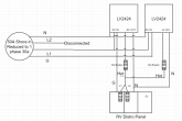
Each unit produces 20a max each. They are tied via communication cables and software to split the load. Thus combined in parallel make a max of 40a to the RV distro panel.
Both guys said this isn't possible nor recommended although its clearly designed for this. And that's why I bought these.
However, I think I found my solution though. Please let me know if anyone sees an issues with this.
Essentially I am dropping 1 leg like a 50a to 30a dog bone would do. This way my 40a will still power both sides of the Rv power panel. Still giving me the ability to turn off of an inverter if I want, or if one goes down. I've already ran the 8/3 wire to do this. Max output of the system is (2) 20a = 40a. I don't expect to ever run over 30ish amps. I think continuous we will see around 20a - 25a with air conditioning running.
View attachment 16402
This handles the ground when plugged into shore power.
Now I need to figure out where and how to add the switchable bonded ground when not on shore power. Does anyone know if the ATS inside these units does this automatically?
lad I asked.
I was under the mistaken impression that you had chosen option#1
I now understand that you have chosen option#3.
Do *NOT* do this unless the manual says you can. The only way this can work is if the two inverters sync their sign waves. If the sign waves are not synced, you *will* blow up one or both of the inverters.
If you are on shore power, the inverters will follow the sign wave from shore and it may work fine. However, as soon as you are on battery, the sign waves will start to drift and all the magic smoke will come out of the inverters.
I went out and found an MPPT manual...but I don't know for sure if it matches your model.Well that's a bit scary.
I decided this route because of this:
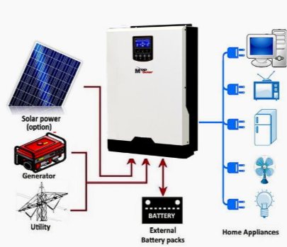
All-in-One Solar Power Packages
MPP and a few other manufacturers now sell a "complete off grid system in a box" that has: AC Inverter Solar Charge Controller AC Battery Charger Automatic Transfer Switch (if grid power is...www.mobile-solarpower.com
I follow his youtube channel, he ran this for several weeks in his RV no problems while testing it.


Yes the 2.4kw model.I went out and found an MPPT manual...but I don't know for sure if it matches your model.
Now that I understand the neutral ground bond this helps so much!
A relay would be super convent, however I think I would need a 50a relay right? The links are for 20a max.
Trying to find a TPDT switch that would work due to high amps. I'm ok with manual switch, because I intend to not be on shore power 99% of the time.
Does anyone know if the ATS inside these units does this automatically?
@smootheJoeyTrying to find a 3PDT switch that would work due to high amps.
Yep. Thanks for the input!The diagram looks correct, but if you forget to throw the switch, the bonding will be wrong.
Using the ampacity ratings in the table you provided, you have a 250A fuse protecting a cable only rated to handle 205A. Worst case it will burn before the fuse blows.The ratings for the cable I purchased are here, well within limits.
Please post an updated diagram.Hey guys I got it all set up everything's running great on the DC side. However... when it's under load of anything more than a 400+ watts the MPP's go into fault mode and turn off. Even when I've got 1200 plus watts of solar coming in the AC side still trips. so I'm thinking it's maybe my wiring going back into the RV distro panel?
I'm not tripping any breakers or anything like that and the rest of the system it's only the MVP controllers that are doing this.
Anyone out there with LV 2424 experience run into this before?
Ramp the AC. Load up as high as you can then look for warm connections. A cheap harbor freight thermal scanner is good for this.
")
All diagrams are posted already. Post #39 on here shows the bonding I did.Please post an updated diagram.
I probably won't be able to see it but others will.
Probably not relevant but how did you end up dealing with the neutral ground bond switching issue?
Do you have a shunt?
I thought you might have changed it.All diagrams are posted already. Post #39 on here shows the bonding I did.
Yes I have a shunt.