Can I fix this by switching the bridges
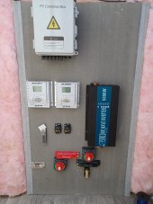
The easiest is to simply take the battery wire connected to the negative bus bar and move it from the upper-right battery to the lower-right battery.
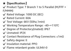
So from the positive bus bar, electricity from the 4/0 wire to the battery would be met with the DC disconnect switch followed by the 375A fuse before hitting the battery? Is 375A what I need? I'm not finding it to be as readily available as a 350A or 400A. Could I use one of those?
battery positive -> main fuse -> main DC disconnect switch -> positive bus bar
Yeah, 375A is an odd size. Since you are planning on 400A bus bars you should go with the 350A fuse. If you ever try to use the full 5kW from the inverter it will be a little tight but not too bad. If you go with a 400A fuse then you must go with a 500A shunt and 500A bus bars.
Will a 75A ANL fuse work here?
I used a Bussman brand 285 series breaker for my SCC. Blue Sea also has a version of this breaker. It can also act as a disconnect if ever needed. If you use a fuse then a MEGA fuse is probably just fine. If you can't find a 75A then 80A will be fine (especially with your 4AWG wire.
Here is a rough of the schematics for the wires, fuses, breakers, and disconnects/isolators.
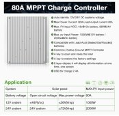
How long will the wires be from the 5-way PV connectors to the SCC?
What is the voltage rating of the breaker you will be using for the PV disconnect? Make sure it is rated for at least 50V or more and for DC.
The wire from the AC-out of the inverter to the AC breaker box is currently labeled as 4/0AWG. It should be the same 6/4 that you have out from the AC breaker box.
Your wiring change for the batteries looks correct but it is just weird. It seems clearer to keep series pairs side by side instead of crossed. Simply change the battery wire from the negative bus bar from the top-right battery to the bottom-right battery. But in the end both approaches work the same. If you ever add a 3rd series pair then your current "criss-cross" approach falls down.