You are using an out of date browser. It may not display this or other websites correctly.
You should upgrade or use an alternative browser.
You should upgrade or use an alternative browser.
Off grid cabin— frozen 48v battery in low voltage and BMS won’t start up
- Thread starter Messier11
- Start date
Do you guys think cell 2 and 3 are problematic?
Looks all good to me.
LakeHouse
Solar Enthusiast
I'm wondering what was in the log earlier than these entries? I'm guessing a cell over discharge protection, and then an automatic power off. I'm assuming this would be logged, but I've never done it on my BMS, so can't say for sure.The log:

The reason I ask is that it might help point to what sort of problem occurred, how big of a problem it was, and when... The first chronological item in the sequence will tell you when exactly the problem started, so you'll get an idea of how long it took to get from you leaving the cabin, to the BMS running into trouble. Then the time from the first item to the second might tell you how quickly the battery was draining. For example, if the cell over discharge occurred, and then the BMS shut down a few hours/days later, you're looking for a small current. But if these two events occurred rapidly (as above, in about a minute), it might have been more than a little drain. Either way the power is small to get from 2.6V (BMS cuts off power) to 2.5V (BMS shuts itself off), but once the first one happens, there should be no more power drain and the second should have taken a long time.
It looks like the situation took a few life cycles off of the cells. I would still run them unless you see those cells become runners.
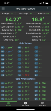
Love the cell volt difference! Maybe this is the new way to balance the cells. Discharge them to 0.6v each in minus 20c, then let them be for a couple of months, then charge them up again! Sounds like a good idea @Will Prowse ? ?
These LiFePo cells can take a beating. We have had many led batteries out here before, they never lasted…
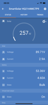
One important thing though, what got the MPPT charging again was (a) removing the communication cable from the JK BMS to an ESP32 that got was connected to a RPI running Home Assistant and (b) removing a communication cable from a 12v EPEver charger to the same RPI.
The system worked fine during the summer, and then the last thing I did was adding these two cables, and within days the MPPT stopped charging. Then I remove them now, and the MPPT starts charging.
Does this make any sense to anyone?
It’s of course not 100% that these cables were the issue, a lot of other things have changed too. The system has definitely rebooted, many devices have been updated, etc. But it does seem suspect and it does seem like I have had some phantom loads… And it is hard to see how those phantom loads could exist if they don’t come through the BMS. Like there is a cable that goes uninterrupted from the negative pole of the battery to the BMS, and there is nothing on it before after the BMS. If the BMS can relay off this cable, then that cannot be the source,
Then you of course have the balancing cables from the BMS to each cell. If power can go through these cables -> to the communication cable from the BMS -> to the RPI which in its turn is connect to the 12v system -> which in its turn is connected to another RPI -> which runs VenusOS and is in its turn connected to the MPPT, the MP2 and the SmartShunt -> it is easy to see that it could create issues.
HarryN
Solar Enthusiast
Good demonstration of the advantage of solar panels on vertical walls.
Good demonstration of the advantage of solar panels on vertical walls.
Good point!
sunshine_eggo
Happy Breffast!
View attachment 136652
Love the cell volt difference! Maybe this is the new way to balance the cells. Discharge them to 0.6v each in minus 20c, then let them be for a couple of months, then charge them up again! Sounds like a good idea @Will Prowse ? ?
No. I know you're not serious, but no. Just in case you've planted an idea in some reader's head.
These LiFePo cells can take a beating. We have had many led batteries out here before, they never lasted…
Nope.
It worked shutting everything off in the BMS, pulling the balancing cable plugs, and putting them back in.
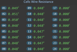
This is how the resistance looked in the summer:
View attachment 136580
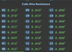
This is how it looks now:
View attachment 136581
Do you guys think cell 2 and 3 are problematic?
I think you've presented evidence of substantial cell damage. Anything with > 10% increase is highlighted.
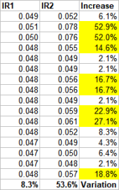
Of particular note is the dramatic increase in IR vs. the average (bottom row, "Variation"). On first measure, all cell IR were within 8.3%. Now they vary by 53.6%.
My hope is that this calculation is iterative, and it may be refined with continued use under different loads and may normalize over time. Additionally, I would ensure that all bus bars, sensing wires and all other connections are clean, properly crimped, and torqued.
If these values are accurate, you should expect a substantial decrease in cell cycle life and an increased risk of spontaneous cell failure.
The worst-case IR increases are along those lines of what you would expect from a battery after several years of service.
@RCinFLA what do you think?
Last edited:
dramatic increase in IR
These are not internal resistance though, they're the wire resistance of the balance leads. I wouldn't be surprised that the difference is because of temperature cycles and the bolts slightly loosening/moving. Also, the cell wire resistance on this BMS is something that needs to be calibrated/can be set. I wouldn't trust those numbers as indication of anything except maybe a bad connection of the wire/bad crimp on the connector.
sunshine_eggo
Happy Breffast!
These are not internal resistance though, they're the wire resistance of the balance leads. I wouldn't be surprised that the difference is because of temperature cycles and the bolts slightly loosening/moving. Also, the cell wire resistance on this BMS is something that needs to be calibrated/can be set. I wouldn't trust those numbers as indication of anything except maybe a bad connection of the wire/bad crimp on the connector.
I understand the distinction, but cell IR has to be a part of that measurement. If nothing has changed since the last measurement, why would they be so different on some, but not on others?
This isn't about absolute accuracy, but relative values. Why were they all nearly identical the first time around, but now they're dramatically different, and only some of them?
I made the caveat that all connections should be checked, and the nature of this calculation might be iterative, so it might all be premature, BUT I have first hand experience with 80+ LFP cells that have been discharged to 0.6V. Yes, they "fully recovered" in terms of their capacity and ability to hold a charge, but their IR values - direct measure with a YR-1030 - are notably higher (50-300%) than the small group of cells that were not subjected to the deep discharge.
The BMS has a resolution of about 1 to 0.001 Ohms if I remember correctly - you can see the measured values, e.g., 0.052 Ohm. A typical cell this size has an internal resistance of 0.25 milliOhm, so even if you increase the IR with a factor of ten, the measured 0.052 Ohm would become 0.054 Ohm. Typical cell resistances are beyond the capabilities of a BMS to measure; you need something like the YR-1030 to do this.
sunshine_eggo
Happy Breffast!
The BMS has a resolution of about 1 to 0.001 Ohms if I remember correctly - you can see the measured values, e.g., 0.052 Ohm. A typical cell this size has an internal resistance of 0.25 milliOhm, so even if you increase the IR with a factor of ten, the measured 0.052 Ohm would become 0.054 Ohm. Typical cell resistances are beyond the capabilities of a BMS to measure; you need something like the YR-1030 to do this.
I understand I may be extrapolating meaning. Will you be concerned if these values remain high compared to their prior values after all connections have been cleaned, checked, etc.?
I understand I may be extrapolating meaning. Will you be concerned if these values remain high compared to their prior values after all connections have been cleaned, checked, etc.?
I've had similar situations where the BMS reports much higher values after a power cycle. Also, mine are about twice as high as the ones he has.
Even if they remain at these values, the test I would do is put a load on the battery, and see what the cell voltages do. If the ones that measure a higher resistance sag deeper compared to others under this load, then I would consider these damaged and the measurements relevant. Before that though, it's too early to tell, unless @Messier11 has an IR meter like the YR-1030 for these cells. With current data, I don't consider these measurements of the BMS really indicative of anything.
A little update and some questions!
1. Got out to the cabin, and everything worked fine. The battery shut down due to low voltage in mid November, not odd, the sun doesn’t go over the horizon for my panels by then. Think we could have had snow too.
Last year, the batteries had emptied. When I got it going again, a cable burned up between the Smart Shunt and an Rasberry. During the spring, the MPPT wouldn’t load the batteries.
The only cable that potentially could circumvent the JK and empty the battery was the communication cable from the JK to a raspberry PI. If this cable could send electricity from the battery to the raspberry, it could explain why the cable between the raspberry and the SmartShunt burned up.
After I removed the communication cable from my JK to the Raspberry, everything started to work again and as mentioned, the batteries had not emptied.
I would think twice about hooking up a JK BMS with a communication cable (RS485 or whatever it is called) if the battery might run low!
Don’t know if anyone else had problems with it this?
2. When I started loading my battery, the settings of the JK was all over the place!! -20 UVP?? Calibrating current — 27A? I can’t speak, I am so shocked. ?
What is this?
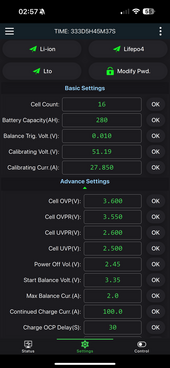
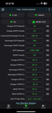


-20 UVP
UTP --> under temperature protection. You should set that to 5C or something above 0C
Calibrating current — 27A
Normal.
I would think twice about hooking up a JK BMS with a communication cable (RS485 or whatever it is called) if the battery might run low!
Yes, this is possible. You also have a BMS shutdown setting where the BMS itself will power itself down to prevent draining the battery after a low voltage event.
Similar threads
- Replies
- 2
- Views
- 218
- Replies
- 59
- Views
- 1K
- Replies
- 0
- Views
- 90


