diy solar

diy solar

Off grid cabin— frozen 48v battery in low voltage and BMS won’t start up

A BMS that has turned off discharge due to low voltage should draw very little power. The Overkill Solar BMS has been documented as being able to run for months. I know that's the the BMS in question here, but...

Shortly after I left the cabin in the summer, I could see through the remote monitoring that I started having issues with the charging from the MPPT. I have no idea why. Anyway, the battery fairly fast shut down itself, and I got to the cabin for the first time in 6 months yesterday.
Draining for 6 months.
 
I would need to by-pass the BMS right?

Is it very bad to charge it with too much current instantly? I am not sure I can access the charge settings without a laptop…

Do not bypass the BMS yet.

As I recall, the charge settings have to be set through Victron Connect. I did it using my laptop via the MK3 interface. You can poke around with your VenusOS device to see if charge settings are available but I don't think they are. Only the AC amps in are changeable on my Cerbo GX. That may be they way. If you set the AC amps into the Multiplus to a low value, say 10 amps, it should restrict the number of amps you can charge the battery with.
 
Ok, so even if the BMS would consume 1W (which it doesn't, it's less), and assume we have 150 days on the battery without any charge source, it would still only consume 3.6kWh total. The pack is 15kWh...

At what point?
I do not know.

It's configurable in the app. I don't remember the default...
 
The recovery number should be what the BMS observes within the system, not what it is seeing from the cells, right? If that's the case, sufficient voltage on the system (from the Multiplus) should bring the BMS back to life.
 
The recovery number should be what the BMS observes within the system, not what it is seeing from the cells, right? If that's the case, sufficient voltage on the system (from the Multiplus) should bring the BMS back to life.
I believe that is correct, for a JK BMS.
(Without the external relay option)
 
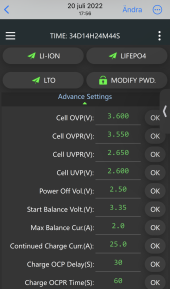
My settings for those by the way are 3.0V for low cell voltage (3.25V cell recovery I think, not sure) and 2.8V per cell where the BMS shuts itself down.
1677192288964.png

I printscreened this in the summer, it’s 2.5v shut everything off, right? Maybe must get the overall voltage to 40v to get it to start…
 
View attachment 136411

I printscreened this in the summer, it’s 2.5v shut everything off, right? Maybe must get the overall voltage to 40v to get it to start…
According to JK’s documentation for the 17S, 20S, and 24S BMS’s, the BMS requires 40V to run. The +5V to start the BMS is called out specifically: “5V higher than that of the battery”. So somehow you’ll need to get to 40V on the battery before the BMS will do you any good.
 
Still weird your cells dropped that low though...
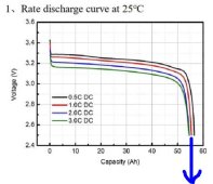
Weird? Well, considering how steep is the voltage profile below 10% of charge for LFP cells it seem normal to me. There is very little energy left below2.5V.
Especially with those little energy vampire connect to them (aka BMS).
And it's worst in the cold.

I rarely use LFP cells in the last 10 years (more before), but I would not be shy to stop discharge at 3V or even 3.1V per cell to have a bit energy left in a solar application (it's different for EV considering large discharge load and voltage sag).

LFP discharge curve.JPG
 
Weird? Well, considering how steep is the voltage profile below 10% of charge for LFP cells it seem normal to me. There is very little energy left below2.5V.
Especially with those little energy vampire connect to them (aka BMS).
And it's worst in the cold.

I know there is, but the BMS shuts itself down so there wouldn't be any vampire loads anymore. I also have tested freezing LiFePO4 to -20C in the past and have not seen a voltage drop to the numbers he's seeing.

stop discharge at 3V

Yes, that's what I suggested above as well.
 
I fired up the generator which started the JK BMS. I am charging now at 28A, it was higher for a little while at first before I got to the settings, but not by that much (perhaps 50A).

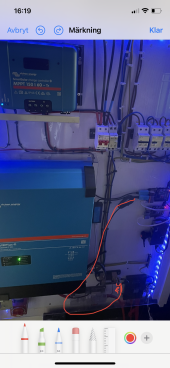
Everything is working, but for some reason the wire between the Smart Shunt and RPI burned up which was a bit scary. But after removing that, everything is fine. Might have been a short in that cable. There is also too high resistance in one of the balancing cables.

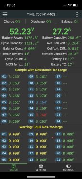
This is how it looks right now:
8E145CF7-6DBD-408B-9598-1F5B9FC75AE6.jpeg

The log:
1677243297129.png

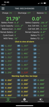
This is the first print screen I got from BMS, the generator is running here, does that boost the voltage? The readings are higher than I got directly between cells most positive and most negative poles.
773CD6E7-4814-42A5-B6CC-7E043D0981EA.png
 
There is also too high resistance in one of the balancing cables.

Considering this is shown as 0, a power reset of the BMS might fix this. But this might also be related to the low cell voltages. See if they get back up and stay up first...

the wire between the Smart Shunt and RPI burned up

Doesn't sound good.
 
So the burnt cable before I pulled it (older picture) (ie the tiny cable hanging down from the SmartShunt):
B7F4DFF6-3D55-4850-B9F9-3A1B34D3E98B.png

It goes from the communication port of the smart shunt to an RPI. The RPI is also connected with USB cables to the MPPT and the MultiPlus 2. The RPI is powered by my separate 12v system. Within 10 seconds after I turned on the breaker from the running generator, this cable started smoking a lotand the isolation over entire length of the cable is melted.

The RPI wasn't damaged (!). Nor the SmartShunt.

What type of current is needed to get that affect? If it was the USB cable that short circuited in the connection I have made, where did this type of current come from?
 
Back
Top