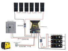
I attached a pic of the system diagram I made. Not sure on the amount of solar yet but will probably be around 4-5 kW in one series string. Please take a look and let me know if anything needs correction or any suggestions for improvement. One question I have is do I need to install a grounding rod and if so where do I attach it to the system? Also do I need some kind of breaker between the generator input and the inverter? If so what should I use for that? Thanks!


You are using an out of date browser. It may not display this or other websites correctly.
You should upgrade or use an alternative browser.
You should upgrade or use an alternative browser.
Planning my first off grid solar build & have a couple questions
- Thread starter PhantomF
- Start date
EastTexCowboy
Solar Wizard
Are you completely off grid? I'm assuming so since you're showing only generator input and no AC input. If not, can you confirm the panel you're showing is a separate load panel from your grid fed panel?
You'll absolutely need a ground. Assuming this is completely off grid you'll need an N/G bond in the main panel. The ground in the panel should have an earth ground (ground rod) then your system should be grounded to the ground in that panel. You should also ground the frames of your panels. Opinions vary depending on how far away the panels are located but I would ground the panel frames to the same system ground and avoid two separate ground rods.
If, on the other hand, you are trying to feed an existing main panel that is attached to the grid your system as drawn is not going to work unless you have an interlock or some other method to isolate your solar AC output from your grid fed circuits.
All this said, I'm not an electrician but there are plenty on here, which is where I've acquired at much of this knowledge.
Are you completely off grid? I'm assuming so since you're showing only generator input and no AC input. If not, can you confirm the panel you're showing is a separate load panel from your grid fed panel?
You'll absolutely need a ground. Assuming this is completely off grid you'll need an N/G bond in the main panel. The ground in the panel should have an earth ground (ground rod) then your system should be grounded to the ground in that panel. You should also ground the frames of your panels. Opinions vary depending on how far away the panels are located but I would ground the panel frames to the same system ground and avoid two separate ground rods.
If, on the other hand, you are trying to feed an existing main panel that is attached to the grid your system as drawn is not going to work unless you have an interlock or some other method to isolate your solar AC output from your grid fed circuits.
All this said, I'm not an electrician but there are plenty on here, which is where I've acquired at much of this knowledge.
Thank you this helps a lot. Yeah it will be completely off grid. The generator will be the only AC input just in case the sun isn't cutting it. So it seems I'll need an earth ground for sure and that should connect to ground in the breaker panel. Then the panel will need to have the N/G bonded since it's the main and only panel in the system. Can the ground from the solar panels run to ground in the panel or should that just go directly to the ground rod outside? The panels will be probably around 10-15 feet above the inverter on the roof.
EastTexCowboy
Solar Wizard
I suppose either would work but I would run the ground for the solar panel frames to the breaker panel and ground it there.Thank you this helps a lot. Yeah it will be completely off grid. The generator will be the only AC input just in case the sun isn't cutting it. So it seems I'll need an earth ground for sure and that should connect to ground in the breaker panel. Then the panel will need to have the N/G bonded since it's the main and only panel in the system. Can the ground from the solar panels run to ground in the panel or should that just go directly to the ground rod outside? The panels will be probably around 10-15 feet above the inverter on the roof.
Just to be clear, it's the frames on the panels that are grounded. Not the negative cables on the panels. That may seem obvious but it's something that has come up occasionally.
Hedges
I See Electromagnetic Fields!
- Joined
- Mar 28, 2020
- Messages
- 20,693
Can the ground from the solar panels run to ground in the panel or should that just go directly to the ground rod outside?
You should also ground the frames of your panels. Opinions vary depending on how far away the panels are located but I would ground the panel frames to the same system ground and avoid two separate ground rods.
In particular, there must be a ground wire from panel frames that connects to inverter/scc chassis. If not a direct wire, then connected through other wires. People and dogs here have been shock when it wasn't (some inverters send low current AC into the PV wires, and running ground wire back pulls it to zero volts.)
I would make it direct, not to the ground rod or AC breaker panel ground, because I'd like DC faults to clear or at least be held to zero volts without current through AC system's ground, and vice versa. A DC fault typically will not clear a fuse or breaker, so could just keep delivering PV Isc. If someone working on AC system shut off AC power and disconnected a ground wire, they could get hit with PV Voc, bad news. I would treat AC and DC ground as separate systems, and then connect them together.
When you say you would make it direct, do you mean you'd just run the ground from the panel frames and attach it directly to the inverter chassis box somewhere? If so, where at on the chassis, or doesn't matter where? Also, you said 'I would treat AC and DC ground as separate systems, and then connect them together.' What do you mean by 'and then connect them together'?In particular, there must be a ground wire from panel frames that connects to inverter/scc chassis. If not a direct wire, then connected through other wires. People and dogs here have been shock when it wasn't (some inverters send low current AC into the PV wires, and running ground wire back pulls it to zero volts.)
I would make it direct, not to the ground rod or AC breaker panel ground, because I'd like DC faults to clear or at least be held to zero volts without current through AC system's ground, and vice versa. A DC fault typically will not clear a fuse or breaker, so could just keep delivering PV Isc. If someone working on AC system shut off AC power and disconnected a ground wire, they could get hit with PV Voc, bad news. I would treat AC and DC ground as separate systems, and then connect them together.
Hedges
I See Electromagnetic Fields!
- Joined
- Mar 28, 2020
- Messages
- 20,693
Yes. Either a ground clamp on each PV panel frame that wire runs through, or clamps between PV panels and mounting rails that bite through oxide to make contact (e.g. WEEB), then wire from rails, back to somewhere on inverter chassis. My GT PV inverters have lugs for ground wires, both AC and DC side. See if instructions show ground for DC side in inverter, if not, wherever AC ground connects, or an available screw to metal chassis.
What I mean is I'd rather not wire from PV frames to ground in AC equipment and then have single wire from equipment to inverter for both AC and DC grounding. That could have DC current in AC ground path and vice versa. I prefer to have ground from PV go to combiner box or disconnect switch and to inverter/scc chassis. AC system ground wire also goes to inverter/scc chassis, which results in both AC ground and PV DC ground being electrically connected to each other through that chassis. With an ohm meter they will show continuity, as a single net.
What I mean is I'd rather not wire from PV frames to ground in AC equipment and then have single wire from equipment to inverter for both AC and DC grounding. That could have DC current in AC ground path and vice versa. I prefer to have ground from PV go to combiner box or disconnect switch and to inverter/scc chassis. AC system ground wire also goes to inverter/scc chassis, which results in both AC ground and PV DC ground being electrically connected to each other through that chassis. With an ohm meter they will show continuity, as a single net.
Got it! Thanks a lot very helpful info there.Yes. Either a ground clamp on each PV panel frame that wire runs through, or clamps between PV panels and mounting rails that bite through oxide to make contact (e.g. WEEB), then wire from rails, back to somewhere on inverter chassis. My GT PV inverters have lugs for ground wires, both AC and DC side. See if instructions show ground for DC side in inverter, if not, wherever AC ground connects, or an available screw to metal chassis.
What I mean is I'd rather not wire from PV frames to ground in AC equipment and then have single wire from equipment to inverter for both AC and DC grounding. That could have DC current in AC ground path and vice versa. I prefer to have ground from PV go to combiner box or disconnect switch and to inverter/scc chassis. AC system ground wire also goes to inverter/scc chassis, which results in both AC ground and PV DC ground being electrically connected to each other through that chassis. With an ohm meter they will show continuity, as a single net.
EastTexCowboy
Solar Wizard
I'm certainly not arguing with you because your knowledge is several orders of magnitude above mine, but I'm trying to understand this. If you're grounding your AC to the inverter chassis and you're grounding your DC to the inverter chassis how is that any different than grounding everything to the common ground in the load panel where the N/G bond is? I understand that you're trying to eliminate the possibility of DC current on the AC side and vice-versa, but I don't see how this changes that risk. I'm probably missing something, which is why I ask.Yes. Either a ground clamp on each PV panel frame that wire runs through, or clamps between PV panels and mounting rails that bite through oxide to make contact (e.g. WEEB), then wire from rails, back to somewhere on inverter chassis. My GT PV inverters have lugs for ground wires, both AC and DC side. See if instructions show ground for DC side in inverter, if not, wherever AC ground connects, or an available screw to metal chassis.
What I mean is I'd rather not wire from PV frames to ground in AC equipment and then have single wire from equipment to inverter for both AC and DC grounding. That could have DC current in AC ground path and vice versa. I prefer to have ground from PV go to combiner box or disconnect switch and to inverter/scc chassis. AC system ground wire also goes to inverter/scc chassis, which results in both AC ground and PV DC ground being electrically connected to each other through that chassis. With an ohm meter they will show continuity, as a single net.
Man oh man, I don't want to get too far into the whole grounding discussion. I still have an eye twitch from going though all that last year.

Hedges
I See Electromagnetic Fields!
- Joined
- Mar 28, 2020
- Messages
- 20,693
I suppose some current could flow PV cell --> PV frame --> ground mount --> earth --> AC ground rod --> AC ground wire --> inverter chassis.
But with dirt & ground rod resistance 25 ohms, not much compared to copper ground wire path.
In circuits, there can be shared "ground" or return path, e.g. if analog and digital circuits use same wire to carry power from negative side of supply and reference between chips. Digital usually doesn't care, but analog don't want digital switching currents to cause voltage offset between two devices like sensor and amplifier or ADC.
Similar idea for safety grounds. If an AC circuit shorts and carries 1000A or a few milliseconds, would rather that didn't run through a wire between say SCC and inverter. If PV wire ground and carries 10A (from a 400VDC PV array) continuously (breakers don't trip), I don't want that 10A running through ground wire from main breaker panel --> ground wire --> sub panel --> inverter.
So I would bond main panel, sub panel, outlets, AC ground rod all together with wire.
I would bond DC PV frames, SCC, inverter, possibly battery negative all together.
I would then run a wire between DC ground and AC ground, or rely on inverter chassis as the connection.
As I said earlier, a DC PV fault could deliver Isc continuously through the ground path. If that included AC ground wires (because it went direct to ground rod from PV array), and someone working on AC with all AC sources turned off happened to disconnect ground wire, he could get Voc about 400V to 600VDC.
I don't know what or if code says about this, but I wouldn't rely on code alone if I can think of a fault condition.
If system has isolation switch for both poles PV+/PV- to array, that should interrupt the fault current. But a guy working on AC would have no idea there was an issue.
One I've thought a bit about is battery grounds. SMA Sunny Island doesn't care, isolated or battery negative ground or battery positive ground.
NEC says ground the 48V or greater battery bank.
I have four inverters, one battery string. So I think I need battery negative routed to all inverter chassis, either one daisy chain wire sufficient for catastrophic fuse(s) at battery, or four wires fanning out, sized for breaker in inverter.
EastTexCowboy
Solar Wizard
That mostly makes sense to me, other than earth grounding the negative on the batteries - that's the first time I've heard anyone suggest it. I can see that someone unaware of how the whole system is set up could run into problems working only on the AC side or only on the DC side, but for my situation I can't see that happening. Unless I fall over dead and someone else has to figure it out, and even then I have a binder on top of the inverter with my wiring diagrams, breaker identification, and detailed instructions on how to shut down the system, start the system, and switch it manually to grid. If I'm working on it myself I turn the stuff off then put a meter on it just to be sure.I suppose some current could flow PV cell --> PV frame --> ground mount --> earth --> AC ground rod --> AC ground wire --> inverter chassis.
But with dirt & ground rod resistance 25 ohms, not much compared to copper ground wire path.
In circuits, there can be shared "ground" or return path, e.g. if analog and digital circuits use same wire to carry power from negative side of supply and reference between chips. Digital usually doesn't care, but analog don't want digital switching currents to cause voltage offset between two devices like sensor and amplifier or ADC.
Similar idea for safety grounds. If an AC circuit shorts and carries 1000A or a few milliseconds, would rather that didn't run through a wire between say SCC and inverter. If PV wire ground and carries 10A (from a 400VDC PV array) continuously (breakers don't trip), I don't want that 10A running through ground wire from main breaker panel --> ground wire --> sub panel --> inverter.
So I would bond main panel, sub panel, outlets, AC ground rod all together with wire.
I would bond DC PV frames, SCC, inverter, possibly battery negative all together.
I would then run a wire between DC ground and AC ground, or rely on inverter chassis as the connection.
As I said earlier, a DC PV fault could deliver Isc continuously through the ground path. If that included AC ground wires (because it went direct to ground rod from PV array), and someone working on AC with all AC sources turned off happened to disconnect ground wire, he could get Voc about 400V to 600VDC.
I don't know what or if code says about this, but I wouldn't rely on code alone if I can think of a fault condition.
If system has isolation switch for both poles PV+/PV- to array, that should interrupt the fault current. But a guy working on AC would have no idea there was an issue.
One I've thought a bit about is battery grounds. SMA Sunny Island doesn't care, isolated or battery negative ground or battery positive ground.
NEC says ground the 48V or greater battery bank.
I have four inverters, one battery string. So I think I need battery negative routed to all inverter chassis, either one daisy chain wire sufficient for catastrophic fuse(s) at battery, or four wires fanning out, sized for breaker in inverter.
Hedges
I See Electromagnetic Fields!
- Joined
- Mar 28, 2020
- Messages
- 20,693
I'm just being the messenger, saying what I've read elsewhere, when it comes to battery grounding.
I do understand that automotive systems switched from positive to negative ground (chassis being a current carrying conductor) for corrosion reasons. But I can see where grounding battery system allows for clearing faults and avoiding anything becoming unexpectedly electrified.
 www.csemag.com
"For the battery system, NEC Article 250 Part VIII, Direct-Current Systems, applies. Refer to Figure 4 for a typical grounding configuration. For this battery system operating at greater than 500 Vdc, ground is not required to be grounded. Article 250.162, Direct-Current Circuits and Systems to be Grounded, applies to systems operating at greater than 60 V but not greater than 300 V. Grounding for the battery cabinet is per Article 250.169."
I do understand that automotive systems switched from positive to negative ground (chassis being a current carrying conductor) for corrosion reasons. But I can see where grounding battery system allows for clearing faults and avoiding anything becoming unexpectedly electrified.
Grounded and ungrounded electrical and power system design | Consulting - Specifying Engineer
Learning objectives Identify electrical and power systems that require grounding. Determine the best methods to ground electrical and power distribution | Consulting - Specifying Engineer
www.csemag.com
"For the battery system, NEC Article 250 Part VIII, Direct-Current Systems, applies. Refer to Figure 4 for a typical grounding configuration. For this battery system operating at greater than 500 Vdc, ground is not required to be grounded. Article 250.162, Direct-Current Circuits and Systems to be Grounded, applies to systems operating at greater than 60 V but not greater than 300 V. Grounding for the battery cabinet is per Article 250.169."
Similar threads
- Replies
- 5
- Views
- 272
- Replies
- 16
- Views
- 350
- Replies
- 3
- Views
- 400