diy solar

diy solar

Pre-charge resistor seems crazy

yeah, and you wouldn't believe how big an inductor is necessary to hold off inrush current.

An inductor, saturable to get it out of the way later, was my first thought ... but then I thought better of it.

I figure 0.1F capacitor charged to 50V, about 500 pieces of this inductor could be connected series/parallel to slow precharge to about 0.1 second, 50A. (would also have deleterious effect on step response demanding 100's of amps, something you alluded to.)


Resistor and relay, or transistor, heatsink, voltage ramp. So easy to accomplish (as long as inverter doesn't start sucking current before you're done.)
 
Now is my time to eat capacitors!!! My earlier comments pertaining to precharging completely overlooked the possibility problems originating from super capacitors. These are not micofarads but can be hundre
yeah, and you wouldn't believe how big an inductor is necessary to hold off inrush current.

An inductor, saturable to get it out of the way later, was my first thought ... but then I thought better of it.

I figure 0.1F capacitor charged to 50V, about 500 pieces of this inductor could be connected series/parallel to slow precharge to about 0.1 second, 50A. (would also have deleterious effect on step response demanding 100's of amps, something you alluded to.)


Resistor and relay, or transistor, heatsink, voltage ramp. So easy to accomplish (as long as inverter doesn't start sucking current before you're done.)


WOW! I thought I was done with this thread........but this post needs an analysis. I am going to use your assumed numbers although my guess is the input capacitance at the input of an inverter to be in the 100-200 or so microfarads. So continuing with your 0.1 microfarad switched from a 50V source and using the formula

V = I*T/C, solving for T and I will use a peak current of 100A which is unreasonable because of circuit constraints.


T = V*C/100 = 50v*10^-7/100a (10^-7 reads as ten raised to the power of 10 to the minus 7th)

T = 50 X 10^-9 = 50 nano seconds

Yeah and circuit built in inductance will prevent that kind of current in time T. Now I will use a more reasonable capacitance of 200 microfarads and see how long this takes.

T = 50 X 200 X 10^-6/100a = 10000 X 10^-6/100 = 100 microseconds (0.0001 seconds)

Above does overlook the charge vs time for simplicity. By that I mean as the capacitor charges V needs correction Vapplied - V of the capacitor. This is not a big deal.

I don't know what actual capacitor sizes one finds in inverters. This much for sure........I HAVE NEVER EVER HAD A PROBLEM WITH INRUSH CURRENT. I take everyone's word that they had problems and offered earlier that those who have problems do whatever they need to fix the problem.

One last comment about the first line in my earlier post. I started thinking about SUPER CAPACITORS and realized as I was typing they are only available in the 2=3V range that I am aware of. I thought I trashed that post, I did not although it should have been.

Quite a departure from solar panels
 
I am going to use your assumed numbers although my guess is the input capacitance at the input of an inverter to be in the 100-200 or so microfarads. So continuing with your 0.1 microfarad ...

Not 0.1 microfarad, not 100 microfarad. I wrote 0.1 F, as in 100,000 microfarads. Larger battery inverters (e.g. 6kW 48V Sunny Island) are around that, maybe a few times that. It was above the range of my meter when I tried to measure.

We're not talking about inverters and transformers for "firing units", which do have their own particular performance requirements. I'm familiar with those, and the implications of any delay in operation, particularly during certain phases of flight.

My system of four battery inverters is rated 23kW continuous at 25 degrees C, 44kW surge for 3 seconds. It has something in the range of 1F to 2F of electrolytics on the battery side. Those aren't filtering 60 Hz; I measure ripple current coming from the batteries, can approach 100% of instantaneous power delivered to loads. (too bad we mostly use split phase, not 3 phase.) Just the higher frequency switching used to synthesize sine wave.

Supercapacitors likely have much higher resistance and self inductance, but would of course sustain precharge current far longer. There are banks of supercapacitors available, with balancing resistors. Other threads have discussed their possible benefit for our systems. The electrolytic capacitors in our inverters are to filter a few kHz.
 
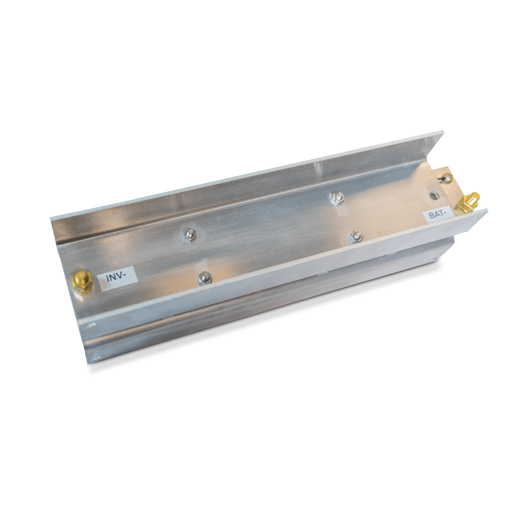
Battle born sells a nifty device to prevent the current inrush of a large inverter. I have one. It works. It is a large chuck of aluminum with stuff sandwiched in between.
 
"FET based device", it says under "Features"


That'll probably work. So long as the inverter gives it time to get the job done. No "power good" status signal so you (or the inverter) just has to wait long enough. BMS FETs could have done it, given enough time an low enough inverter standby draw.
 
I'm intending to buy a Maxwell ultracapacitor (16v) to handle inrush in my 12v bank (funky BMS can't handle it, otherwise they're ok). The choices are 58F and 500F, which one to choose? And would a car audio capacitor (1 - 8F) also work?

How about this super cap jump starter?

 
"FET based device", it says under "Features"


That'll probably work. So long as the inverter gives it time to get the job done. No "power good" status signal so you (or the inverter) just has to wait long enough. BMS FETs could have done it, given enough time an low enough inverter standby draw.

Definitely worth a look.
 
I'm intending to buy a Maxwell ultracapacitor (16v) to handle inrush in my 12v bank (funky BMS can't handle it, otherwise they're ok). The choices are 58F and 500F, which one to choose? And would a car audio capacitor (1 - 8F) also work?

How about this super cap jump starter?
.
We don't know much about its electrical characteristics.
How do you propose to use it (in order to deal with your inrush issue)?
 
.
We don't know much about its electrical characteristics.
How do you propose to use it (in order to deal with your inrush issue)?

 
Is the problem that when you connect your lithium battery with funky BMS to inverter, BMS shuts down due to inrush?
If so, how do you plan to use a supercapacitor to help with that?

Or, is your problem that battery with funky BMS can't handle starting surge of a load the inverter is powering?

"I have a 12v battery with a finicky BMS that doesn't particularly like the startup surge when I turn on my PC."
Ah, some sort of inrush of the PC power supply (or maybe current draw of a load powered by the PC power supply.)

1) How many watts continuous does the PC draw? At 120V?

I'm thinking just plugging it into a long extension cord might be enough resistance to solve the problem.
A thermistor might do it too (but needs to be packaged so its heat doesn't cause a problem.)
If it could have a precharge resistor in the AC line, bypassed after a second, that might do it too.
 
Is the problem that when you connect your lithium battery with funky BMS to inverter, BMS shuts down due to inrush?
If so, how do you plan to use a supercapacitor to help with that?

Or, is your problem that battery with funky BMS can't handle starting surge of a load the inverter is powering?

"I have a 12v battery with a finicky BMS that doesn't particularly like the startup surge when I turn on my PC."
Ah, some sort of inrush of the PC power supply (or maybe current draw of a load powered by the PC power supply.)

BMS is ok with inverter inrush, 3kw, even without pre-charge resistor, but those days are behind me. I have another 5kw inverter, but I always use a pre-charge resistor with it. The BMS can start an inverter-type AC without any problems, but I've learned that inverter-type appliances have relatively lesser inrush.

It's just when powering the PC on. When the PC has already turned on before hooking it up (it has a UPS, so when hooking up the UPS), there are no problems, even with the aircon also hooked up.

1) How many watts continuous does the PC draw? At 120V?

Ours is 220v 60Hz. Power supply is 850 watts rated 80% gold, connected to an APC UPS before the inverter. APC PowerChute reports 160w - 220w during use, or thereabouts. The AC does 500w - 700w, so total load would be about 1kw.

I'm thinking just plugging it into a long extension cord might be enough resistance to solve the problem.
A thermistor might do it too (but needs to be packaged so its heat doesn't cause a problem.)
If it could have a precharge resistor in the AC line, bypassed after a second, that might do it too.

(y) I will try the extension cord.

Currently I start the PC up with my 24v AIO. What I don't want to happen is that I or somebody forget that we're starting it up from a 12v inverter, then the BMS goes into protection mode and I need to disconnect the battery out of the parallel connection just to wake it up.
 
Months ago I used a pre-charge resistor as recommended by Will Prowse and others . Worked fine. No spark. My question is .... If i ever disconnect or even switch off my batteries for any period of time would I have to use that resistor again because the capacitors have slowly discharged? Why I ask is I recently I had to disconnect my batteries for a few hours. When I plugged my Anderson connector back together I noticed a small spark. Seems crazy to have a quick, safe disconnect and still have to unbolt cables and use that resistor before you can turn things on again. FYI, My system is kinda small (100AH, 24V Growatt)
I didn't see a reply to you comment, I'll jump in here for a bit, just my 2 cents. Every time you disconnect an electronic device, such as an inverter, charger, power supply, that have capacitors in it, yes is a good practice to pre-charge if all possible. In some cases the spark is small so no biggie but in some cases stuff melts. I always do!
 
Last edited:
Why all the angst? Only have to do it when connecting inverter to the system and takes all of 30 seconds. R100 10W resistor is all you need and once your system is setup you'll only do it during maintenance. Just not worth the spark.
 
Has it occurred to anyone to just run a wire to a resistor to push-button (momentary) switch connected to the inverter.
Some have a fused resistor just left in place, while others use a timered relay.
That's what I've done in the camper, every time I turn ON the main switch, I just press the button first. I see the inverter lights light up, so works like a charm.
 
That's what I've done in the camper, every time I turn ON the main switch, I just press the button first. I see the inverter lights light up, so works like a charm.

The inverter should be turned off when you precharge the capacitors.

Maybe that is what you are describing but couldn’t tell.
 
The inverter should be turned off when you precharge the capacitors.

Maybe that is what you are describing but couldn’t tell.
It's a MultiPlus and its switch is ON, but it's turned OFF via the Touch screen, a "stand by", I guess.
 
Now really, molten metal?
yes, blown off nickel coating on contact surface where lugs bolt down.
Just my humble opinion.
not so enlightened would be the better adjective. See what happened when in my Not so humble opinion I ignored the basics of electricity. as in me not you.
EDIT: A good inverter should be designed to limit inrush and that can simply be done with a small inductor in series with the energy storage capacitor bank.
magnum 4448 PAE, yes a 4.4K pus inverter that is well designed for people with half a brain, but not so much for idiots like you and I.
 
Last edited:
I have a 5KW true sine wave inverter on my boat purchased from Ebay about 4 years ago, cost was in the $400 range. A good inverter for what I need even though it uses an H bridge technology. That sucker has never ever given problems such as a DC circuit breaker tripping during turnon.

It has been years since my circuit design days when I designed inverters, high voltage electronics AND the transformers used in those circuits. Many of my designs are used in the military's Patriot Missile system. My design years during that period were at a major military defense company then located in Wayland MA.
Dude bragging that you did this or that in a different discipline (no matter how esoteric) is like bragging about being unencumbered and winning the special Olympics... yeah you won.... against people with disabilities... not good optics.
 
Why all the angst? Only have to do it when connecting inverter to the system and takes all of 30 seconds. R100 10W resistor is all you need and once your system is setup you'll only do it during maintenance. Just not worth the spark.

I agree for a permanent install. For my RV, I connect the batteries to the system many times, sometimes multiple times a day.
 
Is your system not permanently installed?

If you don't mind my asking, why?

I go get my camper and turn on the batteries and inverter. I turn off inverter to tow it home from storage. I turn on inverter to cool fridge and run a/c while loading, I turn off inverter to tow. I turn on inverter when I arrive at campground. Etc, etc, etc....

ANd when I am doing testing it might go on and off 20 times in an hour.

Turning off the inverter doesn't discharge the capacitors. Disconnecting the batteries from the inverter will allow the capacitors to discharge.
 
Turning off the inverter doesn't discharge the capacitors. Disconnecting the batteries from the inverter will allow the capacitors to discharge.

Ok, whatever. Not sure what the point of all this is. I turn my system on and off and need something to keep the batteries from going into protect. What difference does it make why? If it were in a house, I could care less about a precharge. I'm not. So I care.
 

diy solar

diy solar
Back
Top