12VoltInstalls
life passes by too quickly to not live in freedom
I have trouble reading 250VAC posts. It’s like they are speaking another language.
Welcome to the Metric world!! Muwahahaha!!I have trouble reading 250VAC posts. It’s like they are speaking another language.
He heWelcome to the Metric world!! Muwahahaha!!
It's really weird how much time it takes me to re-adjust to American power every time I get off a boat. What's a neutral? Why does it need a ground?!?! OMG THIS IS STUPID!!! ?
If you leave the precharge on all the time, you always have a leak circuit. It will drain the batteries @ 2A if you use a 6 ohm/25W resistor like I have. I guess you could flip the switch off every time you shut down, but that is why I have a momentary switch.Excuse me for insisting, given the lack of answers on the subject of precharge circuits, I will rephrase my question:
Most solutions recommend a "manual" delay or with a relay.
What is the problem with an on-off circuit: a resistor bridging the relay contacts, isolation switches or BMS fet (with a 0-I switch that allows the circuit to be shut down for maintenance)?
-After the main circuit is switched on, by the relay, switch or fet, there is hardly any current flowing through the preload circuit! But by leaving it in service, wouldn't we protect the main contacts from the induction choke effect of an untimely cut-off, while benefiting from the precharge?
Two birds with one stone.
Thanks for the answers.
Not sure I understand your question. An untimely cut of what?Yes, it's elementary, but do you have an answer concerning the protection during an untimely cut?
Is this a figment of your imagination?
If the relay was to open, full load current will flow thru the parallel precharge circuit, well, at least temporarily. Could get ugly until it does stop.Excuse me for insisting, given the lack of answers on the subject of precharge circuits, I will rephrase my question:
Most solutions recommend a "manual" delay or with a relay.
What is the problem with an on-off circuit: a resistor bridging the relay contacts, isolation switches or BMS fet (with a 0-I switch that allows the circuit to be shut down for maintenance)?
-After the main circuit is switched on, by the relay, switch or fet, there is hardly any current flowing through the preload circuit! But by leaving it in service, wouldn't we protect the main contacts from the induction choke effect of an untimely cut-off, while benefiting from the precharge?
Two birds with one stone.
Thanks for the answers.
I don't understand your answer, the current of the parallel circuit will always be limited by the value of the inserted resistor?If the relay was to open, full load current will flow thru the parallel precharge circuit, well, at least temporarily. Could get ugly until it does stop.
Same. I left a spare terminal though for other inverters.I did something of the sort. Used a A-B-BOTH-OFF perko switch as a disconnect. I set the resistor up across A to B, B goes to the batter bank. when I rotate it from OFF to A the resistor charges the circuit, then after 10 seconds I rotate one further to B and it’s on. Now my disconnect and reconnect are seamlessly integrated.
The issue mostly comes up when using LFP batteries or huge banks and that initial fill-up-the-capacitors surge sends sparks and molten metal into your face. Not a fun experience I can tell you.I avoided reading the 5 earlier pages in this thread devoted to precharging an inverter. I don’t understand what the problem is. Lead acid and other large storage batteries are designed to supply hundreds of amperes for minutes so a current slug to charge any large capacitor so the batteries are not at risk. What is at risk charging capacitors??? Us a switch designed for high peak current and be done with it
The issue mostly comes up when using LFP batteries or huge banks and that initial fill-up-the-capacitors surge sends sparks and molten metal into your face. Not a fun experience I can tell you.
The only issue is with battery types that use a BMS.Now really, molten metal? I thought the topic of this thread pertained to inverters not industrial applications such motor starters designed to limit locked rotor conditions (armature's stationary position) when started. I maintain using a switch design for large momentary currents should be satisfactory. And yes, I have inverters on my boat and never ever have I worried about inverter initiating current surges during turn on. Just my humble opinion.
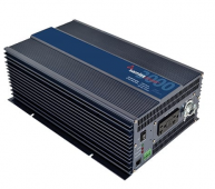
Could you give me an example of a good 12v, 24v, 48v inverter that does not have this inrush with the good design you mentioned in the 3000 watt and above catagory? I could not find one. I have a samulex 3000 watt PST inverter and that's a pretty reputable brand.EDIT: A good inverter should be designed to limit inrush and that can simply be done with a small inductor in series with the energy storage capacitor bank.
Is it connected to a LiFePO4 based battery bank?I have a 5KW true sine wave inverter on my boat purchased from Ebay about 4 years ago, cost was in the $400 range. A good inverter for what I need even though it uses an H bridge technology. That sucker has never ever given problems such as a DC circuit breaker tripping during turnon.
Could you give me an example of a good 12v, 24v, 48v inverter that does not have this inrush with the good design you mentioned in the 3000 watt and above catagory? I could not find one. I have a samulex 3000 watt PST inverter and that's a pretty reputable brand.
I also found that converters, 70 amp 12 volt DC to 35 amp 24 volt, and chargers 120 VAC to 24 volts VDC 35 amps will produce sparks when powered in the DC side at the last point of contact. All three of those together were not pretty. The precharge resistor got rid of the spark for all three devices.
How many watts was your boat inverter? I did not have a sparking problem with the inverter with a 2000 watt inverter, but this appeared at the upgrade to a 3000 watt inverter.
Also, what is the high peak switch you recommend? I used a Blue Sea 350 amp 48 VDC switch on a 24 volt system and got the spark.
EDIT: A good inverter should be designed to limit inrush and that can simply be done with a small inductor in series with the energy storage capacitor bank.
V = L(di/dt).
Which specific switch do you recommend and which specific inverter that will not spark? I don't care about the technical math or to go to deep. Just what you use that is working for you.DC switching-- normally switching DC ''on'' is easy. Switching it off is a problem because all circuits have inductance of some type including wire. That is something that should be corrected in the units design phase. Current in an inductor cannot be changed instantly. This is getting too technical, I will end getting deeper into into the tech other than to share V = L(di/dt). This basic equation shows how a huge voltage will develop if the current is stopped with t = 0 such as opening a switch.

 samlexamerica.com

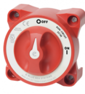
I do think @Hedges is correct on this. I have a Lithium Battery bank for the 3000 watt inverter. The Battery on / off switch pictured above melted away some of the copper on the switch when the battery was turned on and off and created a spark I coudl see through the plastic on the blue sea switch.Inductive kick isn't the issue here. It is low internal resistance of lithium batteries.
Some of us are familiar with inductors.
Inductive kick isn't the issue here. It is low internal resistance of lithium batteries.
Some forum members have blown out class-T fuses simply closing a relay between battery bank and inverter.
I'm not aware of a single inverter designed to limit inrush from battery. I am familiar with transistorized voltage ramp (current limit) circuits used in smaller devices, also connectors with a long pin and precharge resistor.
I'm not presently using precharge because I have lead-acid. Higher internal resistance.
It has been years since my circuit design days when I designed inverters, high voltage electronics AND the transformers used in those circuits. Many of my designs are used in the military's Patriot Missile system. My design years during that period were at a major military defense company then located in Wayland MA.
I did thisSome forum members have blown out class-T fuses simply closing a relay between battery bank and inverter.
Inductor may cause other problemsNow really, molten metal? I thought the topic of this thread pertained to inverters not industrial applications such motor starters designed to limit locked rotor conditions (armature's stationary position) when started. I maintain using a switch design for large momentary currents should be satisfactory. And yes, I have inverters on my boat and never ever have I worried about inverter initiating current surges during turn on. Just my humble opinion.
EDIT: A good inverter should be designed to limit inrush and that can simply be done with a small inductor in series with the energy storage capacitor bank.


