diy solar

diy solar

Really need some help or advice

Or can just scrap the external ATS idea and let the Internal ATS function of the inverters handle the opening and closing of the N-G bond (still have to remove the screw from one inverter)... Then when inverter is providing power it will close the bond, and when it bypass, it will open the bond and the generator will be the new bond upstream...
 
The Kill-A-Watt is super easy to use for Hz reading. Just plug it into the power source, hit either the up or down arrow selector until you see the Hz shown in the display, and that's it, not any harder than that.
I feel kinda dumb now. Holy crap that was easy, clock is getting put away. I should probably play with it some more and see what it can do. 53hz, worse then I thought.

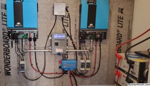
Got the generator unbounded and the transfer switch bonded. The inverters are still isolated and I'm going to remove their screws tonight or tomorrow. I still have to replace a wiring harness in one of my batteries. I'm gonna be busy.
 
Your correct, my house has no bonds. I took photos of all the locations my friend said they should be in, and none are connected or set up.

Called my inspector, he said by code I can only have one ground neutral bond in my set up, and it HAS TO BE, his emphasis, done in the transfer switch. So how does this change things? I know how to do the the transfer switch. But do I now remove all other bonds?
I would ask him again as these are 2 bonded sources. Myself, I'd prefer N-G bond at the source.
 
Take from the thread below:

"Unless you are switching the neutral, a generator is not a Separately Derived System.
See 701 for required standby systems"


Read more about it:
That is why I run a 3 pole double throw for a transfer switch.
 
I would ask him again as these are 2 bonded sources. Myself, I'd prefer N-G bond at the source.
Oh, he knows. He actually told me to unbond the inverters and the generator. I asked him multiple times. He pulled up may plans, asked for pictures of the switch. He said he's going to call the state engineer to be sure and get back to me on Monday. But he said he's sure it has to be "at the house", he's just not sure if it can be at the switch or at the panel. He'd just prefer it at the switch.
 
I feel kinda dumb now. Holy crap that was easy, clock is getting put away. I should probably play with it some more and see what it can do...

Trust me, I had a similar moment, I bought my first Kill-A-Watt many years ago, and it wasn't until several years later, I finally figured out to use it instead of an inductive RPM probe to tune in generator RPM.. I was like, this whole time I already had the better tool right there. I didn't make the connection even though I skimmed past the Hz screen all the time to see 'watts' screen... Now I don't even check the RPM, because I know it's right when the Hz is right, so whenever a neighbor asks me to fix their generator I always bring my Kill-A-Watt with me in my tool pouch. I live in an off-grid community so I fix a lot of generators out here on the co-op.

Another trick on generators, if the volts is out of spec, many of the AVRs (voltage regulators), have a little pot on them (set with tiny screwdriver), usually accessible, if you remove the glue covering it up. Can clean the glue off, and fine tune the voltage if it needs it. Often times I find that the cheaper consumer grade generators are running too low of voltage. If there is no accessible pot on the AVR, the aftermarket replacements have them on there (at least all the ones I've ever put on them when they fail)..

Usually when doing new brushes, many of them have the AVR right next to it on the alternator (under the end-cap where the brushes are), so I tune it in for best correct voltage between both the 240v and the 120v readings, because many times if I go all the way to 120v on each leg to neutral, the I might be up to 249v on both legs, so I find the compromise between both, like say 114v on the low and 242v on the high.

I try to check the volts with around half-load on them and then check them again with no load (make sure they don't go too high due to cheap AVR). Oh, and only set the voltage once the governor RPM (Hz) has already been tuned in to 60 Hz, since too low of RPM can also cause lower voltage.

Also, the above, is all based on non-inverter generators. The inverter generators always maintain the set voltage and Hz, decoupled from RPM...
 
Last edited:
Also, the above, is all based on non-inverter generators. The inverter generators always maintain the set voltage and Hz, decoupled from RPM...
I probably should have mentioned in the previous post mine's an inverter. It's voltage and wattage is fine. But for some reason over time the hz drops, until it dies under load after it over revs.

I'm convinced it's because they are using modified sine wave, and I've been told induction (I believe) motors send rf feedback that eventually destroys them. I removed all motors off this one except the well, and it's lasted twice as long. I've also learned that extended warranties are actually pretty nice.

Well if it's an inverter type generator, then RPM shouldn't make a difference with Hz. On those ones, they can run at low RPM, and ramp up engine speed when more current is being called. If it can't hold Hz stable all the time, perhaps it has a bad inverter board in it. I had troubleshot a failed inverter board on one of my neighbor's generators (his wouldn't create output at all though), but they are not bulletproof, have electronics that can fail too, and boards are usually spendy unless you can find a used one, which may not be far from failing too. Of course your extended warranty is very good to have with these, since they have more electronics involved.
 
Last edited:
Oh, he knows. He actually told me to unbond the inverters and the generator. I asked him multiple times. He pulled up may plans, asked for pictures of the switch. He said he's going to call the state engineer to be sure and get back to me on Monday. But he said he's sure it has to be "at the house", he's just not sure if it can be at the switch or at the panel. He'd just prefer it at the switch.
I guess you can bond at the transfer switch for inspection, then change it later. ;)
 
I went back to the installation photo. Did you install the gray cable that is for use with 240V split phase? Do not install the other cables.
 
I went back to the installation photo. Did you install the gray cable that is for use with 240V split phase? Do not install the other cables.
Yea, the communication cables. They were on before turning the units on.

I plan to start up in the morning. I'm trying to get stuff out of the way on the generator so the batteries can charge.
 

Attachments

  • 20231104_145806.jpg
    20231104_145806.jpg
    1.7 MB · Views: 7
  • Like
Reactions: Zwy
@Samsonite801 @Zwy @pvgirl
Thank you all for your help, I'm very grateful for your time. My system started up, and I'm currently powering my house.

I guess you can bond at the transfer switch for inspection, then change it later. ;)
My neighbor asked why I even got a permit "not like they are going to see lights on in the window and stop by with a 'do you have a permit for those lights?'." I'm like the only one in the neighborhood that got a permit for their solar.


I got a couple of questions on the inverters if any can and has time. It's running at 119v, is that because of my dead battery? Current Connected said it was dead an I'd need to charge it. Does both my inverters need to be set to ply, or just the one talking to the batteries? I have just the one programed ATM. And is the load meter in relative to the entire system, or just that inverter's leg? Thanks again to you all.
 
@Samsonite801 @Zwy @pvgirl
Thank you all for your help, I'm very grateful for your time. My system started up, and I'm currently powering my house.


My neighbor asked why I even got a permit "not like they are going to see lights on in the window and stop by with a 'do you have a permit for those lights?'." I'm like the only one in the neighborhood that got a permit for their solar.


I got a couple of questions on the inverters if any can and has time. It's running at 119v, is that because of my dead battery? Current Connected said it was dead an I'd need to charge it. Does both my inverters need to be set to ply, or just the one talking to the batteries? I have just the one programed ATM. And is the load meter in relative to the entire system, or just that inverter's leg? Thanks again to you all.

What's your battery voltage at? What's the SoC being reported on the BMSs when you direct connect the shelves with a computer?

On the battery settings, you should set the inverter having the comms connection appropriately for the battery comms protocol, and set the adjacent inverter to USE (at least that's the way you do it on EG4 that I've seen). I still haven't set up comms on my MPP Solar, but I might try that (if you are getting some comms error in the display)...
The dead battery is at 5v, and the BMS won't turn on. It's not charging at all, it's likely going to need a new BMS or will be replaced. I'm just wondering as I've had something similar happen on my cabin.

I'm not getting any errors I think. I assume the flashing battery icon means it's being charged or discharged, I'm still learning.


At least on the EG4 6500EX anyways, the flashing battery icon on the inverter with the comms connection means the comms link is communicating. Again not sure on the other variants of the 6548s, but I might assume they have the same indication..

If that battery has low voltage, you might lookup in the manual or contact the manufacturer and ask them if there is a procedure to reset the BMS, or you might be able to take the cover off and charge up the cells manually (with a power supply or other supply voltage), up high enough to allow the BMS to turn on again.

Usually on the newer BMSs, if the volts go too low and they disconnect, they would still allow charging, but not discharging. But perhaps this BMS has shutdown both, or the voltage is not high enough for the BMS to even turn on or operate at all. Perhaps it has a dead cell or something too?

Is that just one battery shelf (with low voltage) and all your others are fine?
 
Last edited:
At least on the EG4 6500EX anyways, the flashing battery icon on the inverter with the comms connection means the comms link is communicating. Again not sure on the other variants of the 6548s, but I might assume they have the same indication..

If that battery has low voltage, you might lookup in the manual or contact the manufacturer and ask them if there is a procedure to reset the BMS, or you might be able to take the cover off and charge up the cells manually (with a power supply or other supply voltage), up high enough to allow the BMS to turn on again.

Usually on the newer BMSs, if the volts go too low and they disconnect, they would still allow charging, but not discharging. But perhaps this BMS has shutdown both, or the voltage is not high enough for the BMS to even turn on or operate at all. Perhaps it has a dead cell or something too?

Is that just one battery shelf (with low voltage) and all your others are fine?
Its just the one battery out of the 10, I'm doing a single bank as opposed to my diagram. When I wrote it, I didn't know they need to be a single bank for communication. I've been in contact with Current Connected, they are SOK batteries so they'll like just send me a new BMS to replace.

I don't think its a big deal. It's just the generator was pretty solid at 120v, the inverter fluctuates more on voltage. But solid 60hz, so everything is running normal again.
 
First thing is hit this link: https://diysolarforum.com/resources/grounding-and-bonding-the-mpp-lv6548-inverter.323/download

Study diagrams 5,6,7 and 10. Mine is wired similar to diagram 10 with a 3 pole transfer switch. The location of the bonding screw is shown on page 18. You will need to determine where your system N-G bond will take place and whether the generator bonds N-G as this will affect how to bond your system.

Your thread reminds me of this thread. https://diysolarforum.com/threads/lv-6548s-split-phase-not-awesome.54708/ where several inverters failed at power up.

While the EG4 6500EX is similar, bonding is handled differently. In the settings, there is no an option to turn dynamic bonding on/off. The LV6548 does not have this setting.
Diagram #10 shows grounds from the inverters going to nothing in the transfer switch. I figure it is a drawing error as there is no need to run ground from inverters.
 
Diagram #10 shows grounds from the inverters going to nothing in the transfer switch. I figure it is a drawing error as there is no need to run ground from inverters.
The reason he drew that in figure #10 was he had read in the NEC an EGC had to run with the current carrying conductors. I remember that discussion, it was about code compliance if an inspector was to catch it. If an EGC was run and connected at the transfer switch, it would create a ground loop, thus it just dead ends there.

I did not wire my system that way. The EGC enters the inverter AC input with current carrying conductors from grid power. I did not run an EGC from inverter output. I didn't see the need to run a wire to nothing.
 
Back
Top