diy solar

diy solar

Relay with a chargery bms?

Bleedingblue

Solar Enthusiast
Joined
May 12, 2020
Messages
544
Do you have to use a relay with the chargery bms? If so what kind?

I have 4 banks of batteries with a chargery 300 amp on each one. Where is the relay placed?


Do I need 4 of these relays?


As far as breakers can I use 4 of these? I guess I would need 8 of them since I have 4 sets of batteries going to a copper bar and then 4 hybrid inverters all connected to the bar as well to draw battery power from?


Or maybe a fuse type?

 
The Chargery DCC would probably be a good solution for you ..... @Steve_S has a setup with multiple packs ... maybe he will check in an see this.
Will probably need more info about your system, charge and load devices and how much current you expect.

The SSR's like the DCC will use less power from the pack. There's a thread about the DCC here.

And another SSR thread here.
 
That is some mind warping stuff right their trying to understand lol


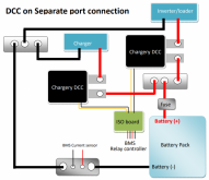
Dcconseparate.png


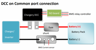
DCConCommon.png


I don't understand why @Chargery doesn't sell this as options as part of a bms kit.

I have 4 of the 300 amp 16s bms and know someone right now that needs 2 bms for their 48 volt banks.

Would be awesome if they included a fuse, external power board, this DCC, wires and wiring diagram that is easy to understand for the DIY guy. Because no solar installer around here will touch any of this stuff.
 
A fuse depends on whatever equipment is attached. IE a 1000W versus a 5000W Inverter = much different amps pulled. Multiple packs sharing a DC bus or one pack only ? all depends on end user setup.

The ISO Board & External Power Interface boards are NEW, as in last fall and are a result of our input regarding issues / quirks etc. The DCC's are a direct result of a few of us here doing tests & evaluations and even having custom SSR's (500A/1000A) made and more. Jason decided to develop the DCC to suit our needs & wants. He has sent out ISO & External Power boards to folks who have asked and I believe he's included them with orders after they were developed and released.

Common-Port is the most common & simplest method of connection. Separate Port is more in line with ~EV'S~ as they most often have an independent Inverter and an independent Charger which require seperate port management. ESS (Energy Storage Systems) are most often connected to combined Inverter/Chargers and an SCC (Solar Charge Controller) as well on a common DC Bus.

The new P Series BMS' coming are incorporating a lot of ideas, requirements and upgrades as suggested by us here, such as Active Balancing, better comms, 16bit sampling and much more. Expected to be released in March.


Ok so I should hold off on buying anything else? And tell the person who needs 2 of the bms to wait?
 
Has anyone ever “and”ed the two Chargery BMS outputs to one relay? I mean if I have a gigavac relay and want to shut off if the pack is too high or too low using ONE relay.
 
I would love to say something snarky like I read the 16s bms manual completely... but I think I did and I don't remember seeing that in there... never the less... there it is.... cool and thank you. :p
 
Just to log a solution into the forum.... I asked the other day about combining the CHG and DISCHG outputs from the Chargery BMS to ONE relay. The manual offered a solution of using some opto isolated relay board that actually ends up driving two electromechanical relays... not optimal.

I ordered some $3 optoisolated DC relays from ebay. https://www.ebay.com/itm/322209858572 3-32V DC 1-Channel SSR Solid State Relay High-low Trigger 5A 5v 12v For Arduino . The input of this relay module requires 12v and a ground and a 12v switched input. So I connected the chargery black wire to the DC- and either one of their red wires to the DC+ input. The remaining Chargery red wire goes to the CH1 input on that relay module. If chargery drops either of the CHG or DISCHG 12v's, the relay module will not operate. So this is a very simple $3 low current draw solution to combine the two outputs from the chargery.

Depending on how I end up feeling about the chargery BMS, I may end up using the above isolator and the gigavax GV241FAX for my contactor.

As it is, I have a battery pack just sitting doing nothing but running the chargery BMS and it has run mybattery down to 53v from 55.8 two weeks ago... no problem.... but.... since the shunt isn't calibrated right, it shows 1a charge even though it should say "storage" mode. Because of this the SOC counter is NOT registering the voltage loss as a lower SOC. It still shows 14340wh available.

I really hate to have to say this... but I gotta give up on the chargery DCC. I LOVE LOVE LOVE the idea of a bidirectional switch. But the soft start only works when you manually turn the DCC on. If the BMS commands it off there is no soft start when the BMS commands it on again. This caused me to blow up my first DCC. So I ordered another one and two more BMS's and two more DCC's. I replaced the shorted out DCC with new and the isolation board lights started to flash. I replaced a 3rd DCC and it also flashes LEDs. It may be the ISO board that is killing these things. I put one of the flashing DCCs on my bench last night and put 12v on one of the control inputs and the power light came on as expected. I put 12v on the second contorl input and the status LED came on as expected... what wasn't expected was the little puff of smoke that came from one of the surface mount resistors in the rear of the unit.

So I have 4 DCC units... 1)shuts off charging but will not shut off discharging, 2)lights flash when connected to ISO board and little puff ofsmoke, 3)lights flash when connected to ISO board, 4)new in box, afraid to take it out.

As I said, I love the /idea/ of these, but if I can't get these things going at this time, how can I depend on them to protect my batteries when I'm not looking?

To this end I have ordered a QUCC BMS from aliexpress. It has that gigavac look alike contactor on it. I have heard of some issues with that contactor, so I expect that one day I'll have to replace that contactor with the real gigavac GV241FAX or GV241CAX.

Not to be all negative... Jason at Chargery has been emailing me with suggestions for the DCC problems. His emails are ALWAYS prompt and are VERY helpful. Absolutely wonderful support. We're at the point where I gotta mail 3 DCC units to him so they can be repaired and I'm not sure it's worth the postage because I'll just end up with more DCCs that I'll just have to tip toe around.
 
Back
Top