diy solar

diy solar

Replacing FANS inside the EG4 6500EX-48 to make it quiet

My AIO also has holes all around it.
But the fans blow the right way. (Up)
If something so basic is wrong. it makes me wonder what else there might be that isn't so obvious.
I personally think that it was a last minute change in order to add inlet filters. But not sure how they are much of a benefit.(other than marketing) Since we know that the case has plenty of other holes for unfiltered air to be drawn in through.
 
I replaced all 3 fans with silent ones. It's super quiet and is more than tolerable in the TV room. BUT! During the day the unit constantly hits 72C for the inverter temperature. It never came close to this with the stock fans (average mid 40s). So, having wiring ran tomorrow so it can be moved to another room and putting the original fans back in.
 
Yeah, the noise level is a bit... surprising... in a small cabin environment. Pretty intense even at idle. I'm going to go ahead and insulate my utility closet area with rock wool insulation. I think that will be very helpful in cutting down the noise level heard around the rest of the cabin. Anything that could be done to reduce that noise and still meet the thermal needs would be helpful. Even just making it temp based not power based would be a nice change. My place is cooler much of the year and most of the time it's blowing a lot of cold air when charging or running a moderate load of 1-3KW
 
Generally, a higher powered fan, is going to be more noisy and blow a lot more air.
Silent fans may be silent, but your equipment may also seriously overheat....

Propeller type axial fans are not very good at creating static pressure, and the tip speed needs to be pretty high which is what generates the noise.
Centrifugal fans are much more efficient in every respect.

If you are really serious, fit a centrifugal air blower resurrected from an old room heater.
These have a small diameter very wide barrel type rotor that can shift a LOT of air and run almost silent doing it.
Try heating up a whole room with a pissy little computer fan....

This is the type of thing to look for:
This one is a bit wide, but they come in all shapes and sizes.
Some of these have two speeds, the lower speed will probably be more than enough.
110/220v ac operation should not be a problem with an inverter.
 

Attachments

  • Rinnai_Gas_Space_Heater_blower.jpg
    Rinnai_Gas_Space_Heater_blower.jpg
    104 KB · Views: 10
Last edited:
If the fans are variable speed, some controllers are reading fan speed so make sure any fan chosen will play good with the controller circuit.
 
I replaced all 3 fans with silent ones. It's super quiet and is more than tolerable in the TV room. BUT! During the day the unit constantly hits 72C for the inverter temperature. It never came close to this with the stock fans (average mid 40s). So, having wiring ran tomorrow so it can be moved to another room and putting the original fans back in.
Thanks for running the experiment for us.
 
FWIW, here is the temperature difference with the silent fans vs the stock fans.
 

Attachments

  • IMG_2417.PNG
    IMG_2417.PNG
    197 KB · Views: 90
FWIW, here is the temperature difference with the silent fans vs the stock fans.
was there a significant difference in the noise level. I wonder if adding an auxiliary air handling system to pull the air through them. I use something like this for my resin 3d printing - using the top vents to attach through or even the bottom wiring raceway (if the system has that built on to move the air through
 

Attachments

  • Fan.jpg
    Fan.jpg
    133.7 KB · Views: 25
Yes, it was very significant in reducing the noise. But ran too hot for me. I ended up running wiring to another room from the main panel and back to the sub-panel transfer switch (using the stock fans). So far that's working great.
 
Yes, it was very significant in reducing the noise. But ran too hot for me. I ended up running wiring to another room from the main panel and back to the sub-panel transfer switch (using the stock fans). So far that's working great.
what silent fans did you use, if I may ask? Noctua? model number?
 
Noctua NF-A9 PWM and Noctua NF-A8 PWM.

If you're looking to buy them, I will sell you the set I have. I've already modified the cables to work with the EG4.
 
The fans are loud, but I can deal I guess. Can I add to this and ask about a super high pitched noise that is unbearable. Just switched from a growatt to the EG4 6500 and it has a sound so high pitched I am sure anyone over 40 can't hear it, but I can and it is so loud it is giving me a headache. Gonna power down the system until I get it figured out I think.
 
It’s more likely an artifact of the HF inverter. High Frequency switching can and does produce audible harmonics that some can hear. If it’s that much of a bother, maybe switch to the low freq EG-6000. :)

It would be a great thing for Will to acquire a microphone capable of hearing those high freqs along with measurements for intensity.

And yes, life choices and over 40 have given me the gift of tinnitus, effectively giving my the high pitches ALL the time. :(
 
For cheap experimentation I have both a 2500W high-frequency WZRELB and 2700W low-frequency UPSverter.
- The WZRELB is silent when the fans are off, and the small fans when running are relatively quiet. Then again I am waaay over 40.
- The UPSverter is loud with roaring fan(s) regardless of temperature, and 60hz transformer(s) hum.
 

Attachments

  • UPS Reliable.jpg
    UPS Reliable.jpg
    211.6 KB · Views: 13
if you haven't figured it out yet.

Makes the 'too loud' have a number for how loud - and once you fix it you can make comments like

"Reduced sound level while fans are on by 3db with this change" and make it "scientific"

guess they are a phone app now. Assume Android has an app also.

have not installed my 6500ex's yet so curious if it is something I will be wanting to do soon.
 
A solution is really required to solve this problem!

I've finally wired my 6 inverters in split phase and tested them last weekend and they are unacceptable loud, even in idle mode. They are installed in the garage and the noise level in the house living space is really annoying.

OK, after learning from this thread that a replacement of the fans with quite ones doesn't really work because of too low CFM (under high load), I need to find a different solution.

From my observation, the current fan control in the EG4 6500 is NOT temperature controlled - even in inverter idle, they are really loud and gets much louder under heavy load.

My guess (hope) is, that under low load, the fans would be able to run the most time with (very) low speed (e.g. 10-20%) to keep the units cool enough (also the garage will get two mini splits over the next couple of month to keep it cool). For short peak loads it would be ok, if the fans would be louder to have the possibility to run the fans at full speed if needed and without overheating.

I plan to keep the current fans and want to test 3 separate temperature controlled PWM's for all 3 fans in the inverter. All 3 fans in the inverter are 4-pin versions with PWM control wire and all are currently connected via JST XH2.54 4-pin connectors on the main PCB board of the inverter. So it should be relatively easy to put a controller in between. I found this PWM temperature controller (https://www.ebay.com/itm/382653081487) and want to connect them (3 different) between the PCB JST connector and the fans (it's 12V and max. 3 amp which is enough). The PWM module would get it's power from the existing PCB JST (by unsing only the +12V and GND pins of the 4-pole connector). The fans should be connected to the JST connector of the PWM controller. Each temperature sensor could be screwed to each of the 3 heatsinks which are located above each of the 3 fans (the existing holes in the heatsinks should be useable). The advantage is, that all 3 fans would be controlled by it's own, heatsink specific, temperature.

First, I want to test this on one inverter and want to compare the temperatures with an original inverter with SA under different loads to see how much warmer it may get and how about the noise level. Because I'm using 6 inverters in split phase (200A breaker house system) I hope they will mostly run under very low load (but have enough reserve for short high load situations).

I will receive the PWM temperature controller by beginning of next week and hope I can give you an (positive) update by end of next week. If it would help, I need to rebuild this on all inverters.

The pictures show the JST XH2.54 4-pin PCB connectors for the existing fans and the planned PWM controller. I need to make this work or my wife will give me the red flag ;)

Any other ideas to make these inverters more silent is very welcome!

Screenshot_20230328_123253-PWMController.png
20230328_072212-changed.jpg
 
Last edited:
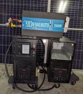
Ok, I've successfully implemented 3 of these PWM temperature controllers between the three existing fans.20230404_210503-marked.jpgOn the right side I've installed two of these PWM controllers for the two inverter unit fans and connected their temperature probes to the two heat sinks (existing holes can be used to screw them on) underneath these black plastic cover/air-channel.

On the left side I've installed the PWM controller for the MPPT fan. To attach the temperature probe to the MPPT heat sink, the PCB on the left side has to be lifted to get access to the MPPT heat sink (remove five screws, but nothing needs to be disconnected). The black plastic cover/air-channel under the PCB can be moved down while temporary remove a plastic plug to access the MPPT heat sink. There is an existing temperature sensor on the MPPT heat sink which could be used also to attach (screw) the additional temperature probe.

The pinout for the three fan connectors (Jst Xh 2.54 4 Pin Connector Male) is unusual. If you look from the top to the inverter PCB, the pinout from left to right is:

blue: PWM
red: +12V
white: sens/tacho
black: GND

So it's important to assign the correct pins to the PWM temperature modules because it's output is more like standard order (GND, +12V, sens, PWD). I made matching custom cables. The PWM pin on the inverter PCB fan connector is now not longer used (blue not longer connected) because the new temperature PWM controller now controls the fan speed. But the "trick" the inverter that the fan is really running, the sense/tacho signal from the fan is still needed on the inverter PCB.

20230404_193705.jpg
The left 3 wires are now connected to the inverter PCB fan connectors. The right 4 wires are connected via an adapter cable to the original fans (with the correct non-standard pinout). To feed the sense/tacho signal back to the inverter PCB I've just soldered the (left green wire) sense/tacho wire to the fan side sense/tacho wire (a bit ugly but it works). WIth this feedback, the inverter "see" the fan running and luckily it does not show error F01 (fan fault) and even with slow RPM (slower than the original RPM), the inverter does not complain.

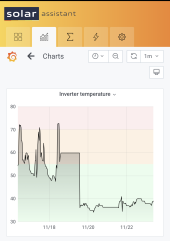
For initial tests, I've programmed the temperature PWM controller to start with the slowest speed and start increasing the RPM starting at 35°C and reach maximum speed when 20°C more are reached (at 55°C). The controller increases the RPM in 19 steps between these two temperature ranges. It can be programmed as needed.

Now I need to do different tests to find out how much warmer the modded inverter will be compared to the original (at idle and different load and MPPT usage) to find the right settings.

For now, I have about 6-8°C higher temperature with the modded version when the inverter just idles at very low RPM.

The modded inverter is now VERY silent without load compared to the original without load!!!

I hope I will see also a lot of improvements even under different load scenarios.

In case I will see good test results over the coming weeks (I still not finished with my installation and can only test them without loads so far) and after fine tuned the temperature settings which are acceptable, I want to implement this change on all six inverters.

I will keep you updated.
 
Back
Top