diy solar

diy solar

Resistor size for precharge circuit

corn18

Village Idiot
Joined
Sep 9, 2021
Messages
676
My precharge circuit has a 25W 6 ohm resistor. Simple circuit shown below. I have 2x12V SOK 206Ah LFP in parallel feeding a Victron Multiplus II 12/3000/120x2 inverter/charger.

When I had the original non bluetooth BMSs in the SOK batteries, this setup worked great. Never had a problem with the BMSs going into protect as long as i precharged.

I have since installed the BT BMSs in the SOK batteries and now the precharge does not work. Trips both BMSs every time. I think the new SOK BT BMS is rated lower than the original non BT, so maybe that is the issue. While I could just swap the non BT BMSs back in, I was thinking about changing my precharge resistor.

No matter how long I hold the precharge button, the BT BMSs still go into protect. My thought is that I am not getting enough voltage to the Victron caps with the 6 ohm resistor and therefore, not getting a full precharge and that trips the SOK BMS. I am thinking that the caps are only getting 2V and that does not allow them to fully charge. If I go with a 4 ohm resistor, they will get 3V and a 2 ohm resistor will be 6V.

I ordered a 2 ohm and 4 ohm to try out, but wanted to check with the experts on here to see if it matters.
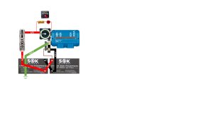
DC wiring 290RL rev 1 precharge.jpg
 
Do you have the inverter power switch in the OFF or in the ON position when you are doing pre-charge?
Try it with inverter power switch is OFF while monitoring the Voltage at the DC input terminals of the inverter to see how high the Voltage rise up to during pre-charge.
Does the SOK with BT have the same discharging rating as the non-BT SOK?
May be there is setting for the surge discharge delay setting in the parameters.

The toggle switch on the inverter is always on. It is not in a place I can get to easily. The remote switch is always off until I want the inverter to operate.

The new SOK BT BMS has the same specs as the old non BT model, but we have tested it and they are different. The non-BT could easily discharge @ 150A and the new one cuts off @ 125A. The surge current is listed as the same, but my testing shows that the old one has a higher rating, but not sure exactly what it is.

Unfortunately, there are no settings that can be adjusted on the SOK BMS.
So you are able to perform the precharge with inverter off then, correct?
The lower the pre-charge resistor the more inrush current, you may want to increase the resistance instead. 12V with 6 Ohms resistor will limit the surge current to 12V/6Ohms = 6A which the BMS should easily handle it with no problem so something is not making sense.
Looking at your diagram, you monitor the Voltage on the output side of the pre-charge switch and the negative of the battery.

The purpose of the precharge circuit is to charge the input caps. Once they are charged, there should be little inrush current, right?
 
The resistor limit the surge current so the BMS will not trip when trying to charge empty cap,s the surge the BMS will see only 2A in this case so that should never trip the BMS, once the caps are charged up to 12V (this why I ask you to monitor the DC Voltage) then you should be able to bypass the pre-charge circuit with that power switch you have.
Are you sure that the BMS trips due to inrush current?
 
Last edited:
You don't need large resistors. I use 68 Ohm 5W and works fine on my HF and LF inverters. Higher the resistance, the lower the charge current.
 
You don't need large resistors. I use 68 Ohm 5W and works fine on my HF and LF inverters. Higher the resistance, the lower the charge current.
Do the inverter caps need a higher voltage to get to full charge? 12v/68 ohms is not a lot of voltage.
 
The cap will be charged up to the applied Voltage, the time it takes to full charge depends on the value of the resistor and the capacitor, so higher resistance or higher capacitance will take longer time to fully charge the cap.
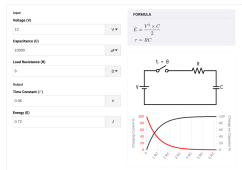
Please read about RC Time Constant, it takes 5 TC for the cap to charge up to the apply Voltage.
 
Last edited:
  • Like
Reactions: JMc
That calculator assumes I am applying the working voltage to the cap. If I only apply 6V to a 12V capacitor, can it fully charge?

I found this on the interweb:

"The higher the voltage rating of a capacitor, the more charge it can hold. To charge a capacitor to its fullest potential, a power supply is needed that can deliver the amount of maximum voltage the capacitor is rated."

That means applying 6V to a 12V capacitor will not charge it fully.
 
But why are you using 6V? Your batteries are 12V so you have 12V system.
You put in the Value of the Voltage source, it does not assume anything.
Capacitor Voltage rating is the max working Voltage it can work up to, you can use 12V rated cap in 6V system with no issue.
 
But why are you using 6V? Your batteries are 12V.
You put in the Value of the Voltage source, it does not assume anything.
The caps see the voltage after the resistor. 12V source, 6 ohm series resistor = 2V at the caps.
 
The caps see the voltage after the resistor. 12V source, 6 ohm series resistor = 2V at the caps.
Where do you get that math from?
I do not think you understand yet how the the cap is charged up and what Voltage you will get on the cap in the RC circuit.
I = E/R
so 12V/6 Ohms = 2A, not 2 Ohms.
See the graph in that TC link I provide once you input the values. I assume 10,000uF capacitor bank.
Example:
1654390846521.png
 
Last edited:
Where do you get that math from?
I = E/R
so 12V/6 Ohms = 2A, not 2 Ohms.
See the graph in that TC link I provide once you input the values. I assume 10,000uF capacitor bank.
Example:
View attachment 97276
OMG! I am an idiot. I was thinking of the capacitor as a resistive load which it is not.

So the answer to my question is no, changing resistor values will not help.

So now on the the next question, what is causing my BMSs to go into protect if the inverter is precharged?

I did do an experiment and unhooked the inverter and I can turn the batteries on with no reset. Then I unhooked everything excpet the inverter and I can turn the batteries on as long as I precharge. If everything is hooked up, the precharge does not work. I checked my DC loads and the only loads that are on are the SCCs and a propane detector.

Weird.
 
Do you have the inverter power switch in the OFF or in the ON position when you are doing pre-charge?
Try it with inverter power switch is OFF while monitoring the Voltage at the DC input terminals of the inverter to see how high the Voltage rise up to during pre-charge.
Does the SOK with BT have the same discharging rating as the non-BT SOK?
May be there is setting for the surge discharge delay setting in the parameters.
For the case of my own Inverter, the pre-charge "mini-spark attempt" only occurred when I attached "12V" and grounding terminal lugs for the first time, through a 25-ohm resistor. (The Inverter was OFF while doing that.) In my travel trailer, current to keep the Inverter's DC Caps charged will be a small but permanent "phantom load".

In making those connections, I used a 25 ohm resistor (bigger than necessary, taking more time). I simply held it between the grounding lug and the grounding cable for 20 seconds. Because I need to do that job only one more time, I now have a spare "high current battery switch" which I will never need to use.
 
So you also have other loads connected to the pre-charge resistor too then.
So the pre charge works OK (just inverter and batteries) without SCCs and a propane detector. The pre-charge should be for the inverter only not with other loads connected. Right now you have pre-charge circuity for the whole system the way you have it setup, when I look at the blue box I thought that is the inverter but now I see it as power distributor box.
What happen if you have SCCs and a propane detector connected one at time?
 
Last edited:
For the case of my own Inverter, the pre-charge "mini-spark attempt" only occurred when I attached "12V" and grounding terminal lugs for the first time, through a 25-ohm resistor. (The Inverter was OFF while doing that.) In my travel trailer, current to keep the Inverter's DC Caps charged will be a small but permanent "phantom load".

In making those connections, I used a 25 ohm resistor (bigger than necessary, taking more time). I simply held it between the grounding lug and the grounding cable for 20 seconds. Because I need to do that job only one more time, I now have a spare "high current battery switch" which I will never need to use.
I use 20 Ohms, and inverter power switch is OFF during pre-charge, the current draw is in mA range when inverter power switch is OFF and pre-charge is done, I only use pre-charge only when I have to disconnect the inverter from batteries and having in the inverter sitting there for hours while troubleshooting the system.
 
So you also have other loads connected to the pre-charge resistor too then.
So the pre charge works OK (just inverter and batteries) without SCCs and a propane detector. The pre-charge should be for the inverter only not with other loads connected.
What happen if you have SCCs and a propane detector connected one at time?
I tried that too and if anything but the inverter is connected, the precharge does not work.

I may will do as you asked and put a volt meter on the output from the precharge and see what is going on with the SCC and DC loads without the inverter hooked up and the precharge switch engaged. Maybe they are doing some sort of parasitic load bringing the voltage down and preventing the inverter from precharging at all.

I may end up having to add a switch for the inverter power and moving the precharge over to that instead of on the main battery switch.
That is what you have to do, I look at your drawing again and now I see that you are doing pre-charge for the whole system not just the inverter (I thought that blue box is the inverter but it turns out to be the power distributor box for the whole system), that is why it does not work, you have form Voltage divider circuit due to other DC loads connected, and if you have check the Voltage you would have seen that the Voltage on the output side of the pre-charge switch will never reach 12V with other DC loads connected.
 
Last edited:
That is what you have to do, I look at your drawing again and now I see that you are doing pre-charge for the whole system not just the inverter, that is why it does not work, you have form Voltage divider circuit due to other DC loads connected, and if you have check the Voltage you would have seen that the Voltage on the output side of the pre-charge switch will never reach 12V with other DC loads connected.
I think you're right. Easy fix.
 
Back
Top