


You are using an out of date browser. It may not display this or other websites correctly.
You should upgrade or use an alternative browser.
You should upgrade or use an alternative browser.
Retired Senior
- Thread starter RetiredSenior
- Start date
RetiredSenior
New Member
Yes I’m looking for input to make the changesThis looks very similar to another thread where @FilterGuy told you that without an interlock this was a dangerous setup. Has anything changed?
Ampster
Renewable Energy Hobbyist
There were a few positive comments and you could start there. Does the block diagram which @Mattb4 posted make sense?Yes I’m looking for input to make the changes
The question I had is which inverter do you have and does it contain an automatic transfer switch? If so, that would change the diagram slightly.
your main issue is the way you are trying to inter connect your 2 panels.
suggestions
1 decide which circuits you can support on the off grid system
2 using wago connectors extend the length of all 3 wires for each of these circuits, hot, neutral, ground
3 use black for hot, white for neutral and green for ground
4 run the 3 wires for each circuit thru conduit from the old to new panel
5 remove old breaker from main panel
6 wire hot in new panel to the CB, and N to the neutral bar and ground to the ground bar
7 wire for 240v from old panel to new panel for inverter AC input ( I think you already did this}
8 remove any other wire from new to old panel, including the neutrals you were asking about
you can not send any power from the new panel back to your main panel
all of this presupposes that your inverter/batt/panels system can not supply all your loads without help from the grid when needed
If your inverter can carry all the loads of your house { I doubt with growatt 6000}
an alternative to all this would be to install a new main panel, have the grid wires moved into this new main panel. Use this new main panel to only power the AC input to inverter and any loads you want to keep on the grid full time. In this case the AC output from inverter would go to your current main panel with all existing circuits
there are 2 ways to run your system
critical circuits in a separate panel
or
whole house. but needs a large inverter with grid into 1 panel, then into inverter and out to the main panel
RetiredSenior
New Member
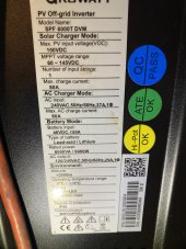
Yes in my mind that was my intention just what you wrote, with no examples to go by, but now it makes more sense to shut off the main breaker and to energize my main panel from the sub panel/ inverter to power my load , this is the inverter I have, and I would not dare to try and to switch any thing on until i knew that it was safe and functional,, I also want to thank those that have added a post that’s moving forward to help me with this project , also thanks to all the others for their negative responses, I understand where your all coming from, I’m probably older then most of you and have tough skin ?I suspect you are correct, an effort to have dual sources of power
I think he wired every circuit breaker in the main panel with an extra wire coming from the sub panel, I guess the plan would be that you could turn off the breaker in the main panel, and turn on the breaker in the sub panel and even with the CB in the main panel off, the circuit would be powered by the sub.
a frankenstein for sure
 ?
?Attachments
rodrick
Free energy enthusiast
One thing I noticed was 40 amp breakers had same size wire as the 15 amp please get a NEC chart for amp ratings for size and insulation rating this will tell you the size of wire and type of wire for the different amp breakersYes I’m looking for input to make the changes
If you manage to burn down your house with that your insurance has a free get out of this magilla card.....no way any insurance company would pay out a dime seeing wiring like that. I would not touch that with a ten foot pole.....liability
It constantly amazes me that people will do wiring like that and think that is safe.
I do not want to be negative but that is way beyond dangerous. My advise is to hire a licensed, bonded, and insured electrician, done with a permit at that point your insurance will be valid.
It constantly amazes me that people will do wiring like that and think that is safe.
I do not want to be negative but that is way beyond dangerous. My advise is to hire a licensed, bonded, and insured electrician, done with a permit at that point your insurance will be valid.
Pierre
Somewhere down South
- Joined
- Dec 21, 2019
- Messages
- 1,132
How about the entire world adopting a standard wiring color code :
Most European countries follow a wire color code established by the International Electrotechnical Commission (IEC) for AC branch circuits. This standard was originally published as IEC 60446, but was merged into IEC 60445 in 2010.
European (IEC) Wire Color Codes
Most European countries follow a wire color code established by the International Electrotechnical Commission (IEC) for AC branch circuits. This standard was originally published as IEC 60446, but was merged into IEC 60445 in 2010.
- Phase 1 - Brown
- Phase 2 - Black
- Phase 3 - Grey
- Neutral - Blue
- Ground - Green with Yellow Stripe
dougbert
Solar Addict
I don't know if it will help but here is my 1 line diagram for my AC portion of my system, it aids in seeing the architecture of what I did

the disconnects and wire sizes are for my house
changes can be made for larger circuits, etc
I have manual transfer switch to allow for inverter bypassing for maintainance
here is the picture of the AC side layout. I use a raceway to contain the various AC circuits between the parts.
the inverter is off to the right side of the raceway
Last edited:
if you insist on powering your main panel from the sub panel with the inverter, then you need a generator interlock in the main panel but that needs an extra breaker in the main panel at top right, and you have no room in the main panel.Yes in my mind that was my intention just what you wrote, with no examples to go by, but now it makes more sense to shut off the main breaker and to energize my main panel from the sub panel/ inverter to power my load , this is the inverter I have, and I would not dare to try and to switch any thing on until i knew that it was safe and functional,, I also want to thank those that have added a post that’s moving forward to help me with this project , also thanks to all the others for their negative responses, I understand where your all coming from, I’m probably older then most of you and have tough skin ?
also if you did that you are setting up an either/or situation. either using all grid or all inverter.
the ability of your inverter to use SUB mode is important and you would lose this option
do you have solar panels or just batteries ?
RetiredSenior
New Member
Thank you, this is a very old house, my wife’s parents and I’m sure the panel was probably from the 50’s, I’m seriously looking into changing it at this point, I am greatly appreciative for all the positive feed back ?One thing I noticed was 40 amp breakers had same size wire as the 15 amp please get a NEC chart for amp ratings for size and insulation rating this will tell you the size of wire and type of wire for the different amp breakers
RetiredSenior
New Member
I have both panels and batteries, I just wrote that I’m seriously changing the panel out , thank you for your positive input it’s greatly appreciated and I know I have many changes to make at this time ?if you insist on powering your main panel from the sub panel with the inverter, then you need a generator interlock in the main panel but that needs an extra breaker in the main panel at top right, and you have no room in the main panel.
also if you did that you are setting up an either/or situation. either using all grid or all inverter.
the ability of your inverter to use SUB mode is important and you would lose this option
do you have solar panels or just batteries ?
Quattrohead
Solar Wizard
The panels are not old and indeed it looks like you have most things required to lay everything out properly.
It's just a horrible mess as it stands.
I would revert the main panel to original and then figure out how to achieve what you want and need.
It's just a horrible mess as it stands.
I would revert the main panel to original and then figure out how to achieve what you want and need.
your welcomeI have both panels and batteries, I just wrote that I’m seriously changing the panel out , thank you for your positive input it’s greatly appreciated and I know I have many changes to make at this time ?
in looking again at your main panel, I dont see a ground bar or any ground wires
can you confirm this ?
are all the outlets in the house the old kind that only have 2 slots ?
maybe all the wiring in the house have no 3rd ground wire, just a hot and neutral, we will have to think about the implications if that is the case
Mike 134
Solar Enthusiast
I see a metal conduit system so no ground wires required. The conduit is the ground. Since this is a service panel the neutral should be mechanically and electrically connected to ground no ground bar would be needed, land all the neutrals and ground wires (if they exist) on the neutral bar. Just a note for you DIYers this is the only place that would be permitted, never in a sub panelyour welcome
in looking again at your main panel, I dont see a ground bar or any ground wires
can you confirm this ?
are all the outlets in the house the old kind that only have 2 slots ?
maybe all the wiring in the house have no 3rd ground wire, just a hot and neutral, we will have to think about the implications if that is the case
Well… I would certainly recommend taking detailed pictures before you try to move anything.I have both panels and batteries, I just wrote that I’m seriously changing the panel out , thank you for your positive input it’s greatly appreciated and I know I have many changes to make at this time ?
I would recommend making a chart of EXACTLY what every breaker controls.
Once that is done, it will be easier to organize everything to be safer and more functional.
If you are planning to replace the panel anyway, perhaps a 60/120 circuit panel will eleminate the need for the sub panel entirely…
good information. thanksI see a metal conduit system so no ground wires required. The conduit is the ground. Since this is a service panel the neutral should be mechanically and electrically connected to ground no ground bar would be needed, land all the neutrals and ground wires (if they exist) on the neutral bar. Just a note for you DIYers this is the only place that would be permitted, never in a sub panel
Looking at this picture, which one is the main panel? The left 100A panel, or the right? Looks like a 100A feed from the left, and the right is being powered from somewhere else?Will Prowse if you could give me you input I would greatly appreciate it.
WILL, My main power is on the left side,, my auxiliary panel that’s connected to the inverter is on the right side, I am back feeding the wires from my inverter auxiliary panel to the main panel circuit breaker wires,, which means that I would have to shut off all the breakers in the main panel from the power source in order to feed the wires from my auxiliary to the house wires! In my mind, I am providing the hot power from the inverter and auxiliary panel to the wires only in the main panel ,,, I so far have not connected a neutral wire from my inverter/auxiliary panel to the main,, as you see I have two wires ready to install into the mains neutral if this is correct ? Can you please advise me if this neutral wire is needed from the auxiliary panel ? Also the ac 240 input on the inverter has line 1 and 2 and shows ground, my feed from the main panel is 2 / 30 amp breakers the does the 3 rd wire go to a ground on the panel? I see that the wiring from the neutral goes out of the box to the water pipe assuming that it’ was built that way many years ago, do I tie into the neutral bar with that ground wire for the inverter ? View attachment 130076
you are correct. the main panel is on the left, the right panel is powered by the inverter, its not really a sub panelLooking at this picture, which one is the main panel? The left 100A panel, or the right? Looks like a 100A feed from the left, and the right is being powered from somewhere else?
the issue was the way he connected the 2 panels to allow house circuits be have dual sources of power, not OK
Similar threads
- Replies
- 14
- Views
- 729
- Replies
- 5
- Views
- 146
- Replies
- 5
- Views
- 200
- Replies
- 13
- Views
- 617