RetiredSenior
New Member
Will Prowse if you could give me you input I would greatly appreciate it.
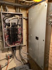
WILL, My main power is on the left side,, my auxiliary panel that’s connected to the inverter is on the right side, I am back feeding the wires from my inverter auxiliary panel to the main panel circuit breaker wires,, which means that I would have to shut off all the breakers in the main panel from the power source in order to feed the wires from my auxiliary to the house wires! In my mind, I am providing the hot power from the inverter and auxiliary panel to the wires only in the main panel ,,, I so far have not connected a neutral wire from my inverter/auxiliary panel to the main,, as you see I have two wires ready to install into the mains neutral if this is correct ? Can you please advise me if this neutral wire is needed from the auxiliary panel ? Also the ac 240 input on the inverter has line 1 and 2 and shows ground, my feed from the main panel is 2 / 30 amp breakers the does the 3 rd wire go to a ground on the panel? I see that the wiring from the neutral goes out of the box to the water pipe assuming that it’ was built that way many years ago, do I tie into the neutral bar with that ground wire for the inverter ?
WILL, My main power is on the left side,, my auxiliary panel that’s connected to the inverter is on the right side, I am back feeding the wires from my inverter auxiliary panel to the main panel circuit breaker wires,, which means that I would have to shut off all the breakers in the main panel from the power source in order to feed the wires from my auxiliary to the house wires! In my mind, I am providing the hot power from the inverter and auxiliary panel to the wires only in the main panel ,,, I so far have not connected a neutral wire from my inverter/auxiliary panel to the main,, as you see I have two wires ready to install into the mains neutral if this is correct ? Can you please advise me if this neutral wire is needed from the auxiliary panel ? Also the ac 240 input on the inverter has line 1 and 2 and shows ground, my feed from the main panel is 2 / 30 amp breakers the does the 3 rd wire go to a ground on the panel? I see that the wiring from the neutral goes out of the box to the water pipe assuming that it’ was built that way many years ago, do I tie into the neutral bar with that ground wire for the inverter ?