diy solar

diy solar

Review My Setup

execv

New Member
Joined
Jul 16, 2023
Messages
9
Location
Utah
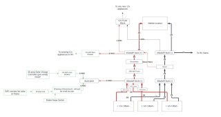
I currently have a travel trailer that has 100w of solar and 2 64ah AGM batteries. I am updating this to a total of 400w of solar and 300ah of lifep04. There is existing wiring for the solar panels/charge controller, brake-away switch, and the 12v system in the rv. I will be adding: a shunt, disconnect, 12v fuse block (for adding new 12v appliances) and 2000w inverter. Can you please let me know if you have any feedback on the plan below. The items outlined in green are the existing items in the RV.
Wiring Diagram (3).jpeg
 
I like to see fuses at the battery. In your case if a wrench drops on either positive bus bar there is no protection. I have MRBF fuses on my battery terminals (similar setup with 3 batteries in parallel).
 
The disconnect in the middle is in a curious spot. What does it disconnect?
Normally disconnects are for battery isolation or for solar isolation.

I would look at having a single bus bar for simplicity, if possible. I do not understand the placement of the 350A bus. Are there space/location factors?

Your batteries, as pictured are not wired in a balanced manner. The bulk of the current will flow thru the rightmost battery (the path of least resistance).
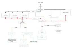
I've updated this to use bus bars, but this seems overly complicated. Am I doing something wrong here?


Wiring Diagram - Page 2 (4).jpeg
 
The shunt positive can go the bus that the batteries tie to. Use the same length wire from the bus to each battery. I question the need for the 200A fuse between the bus and disconnect switch.
 
I've updated this to use bus bars, but this seems overly complicated. Am I doing something wrong here?
I don't see anything wrong but wonder about why it is designed as is.

When would you use the disconnect as located? It does not remove power to anything that would allow maintenance or stop power in completely or power out completely.

When i need to work in something or shut something off, it is almost always a solar disconnect or a batter disconnect.
I suspect as you start wiring this up you will realize that things become powered as you work.
 
Back
Top