robbob2112
Doing more research, mosty harmless
Just putting this thread together as a place for me to post answers to common questions I see over and over.
Whatever you read below is my opinion - read at your own risk -
I found them all in the cellar at the end of the hall in the bottom of a locked filing cabinet stuck in a disused lavatory with a sign on the door saying 'Beware of the leopard.'
If you are new and reading this and have question - please post a new thread.
If you are more experinced and have a correction or disagree with what I have here - post and I'll make the correction if it makes sense.
#1 - how to decide battery voltage and also figure how many panels you need.

 diysolarforum.com
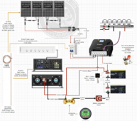
#2 - Sample system - off grid cabin - 24v - 4 panels - bougerv mppt -
diysolarforum.com
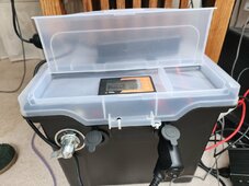
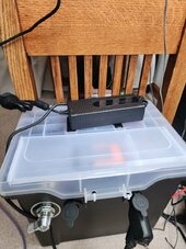
#3 - My CPAP backup unit
diysolarforum.com
#4 - Sample system - 4 x 12v parallel off grid - don't use
diysolarforum.com
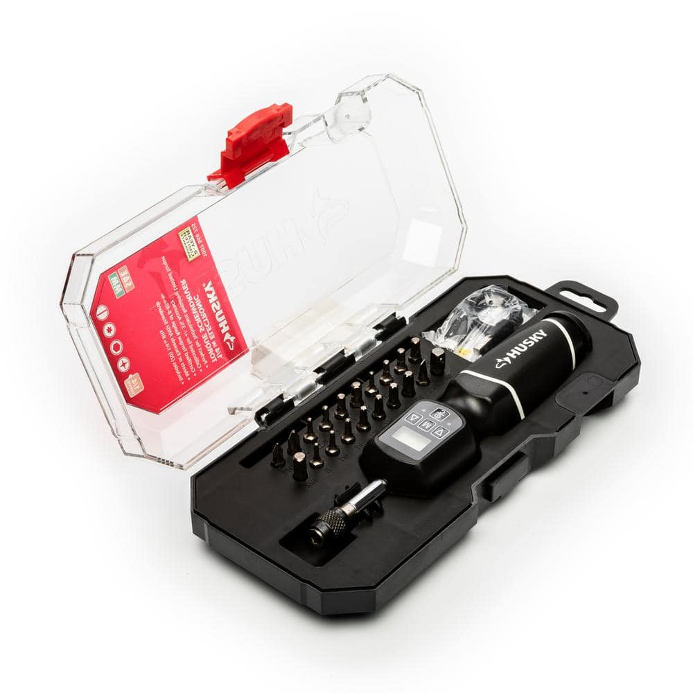
#5 - Tools - Things I have and use - YMMV
diysolarforum.com
#6 - Ferrule usage
diysolarforum.com
#7 - Do you need an equalizer/active balancer with series strings of batteries
Running strings of 2 and 4 batteries - do you need an equalizer - it depends - if you charge discharge the same amount day after day you need an equalizer - if you run totally random patterns that are from 20 to 80% usage every day you don't. BUT, very few actually run a totally random pattern day after day. The sun rises and sets, the ac cycles on and off, etc. So random in the day will delay the batteries but they will get out of sync and require being put in parallel or disassembly and charging individually.
diysolarforum.com
diysolarforum.com
#8 - How to choose system voltage
diysolarforum.com
#9 - What are common types or wire and usage
diysolarforum.com
#10 - Buried conduit - NEC and rules
diysolarforum.com
#11 - Wires on a rooftop
diysolarforum.com
#12 - Fuses, disconnects/isolators, and breakers on PV lines
diysolarforum.com
Good links to read not by me
Hooking multiple batteries in parallel and where on the bus bar to place the uplink cables.
diysolarforum.com
Gasses released by LiFePO4 batteries during a cell vent. I have this one as a PDF, but it is to large to post -- just in case it disappears

 www.ncbi.nlm.nih.gov
Probably the neatest DIY Battery rack I have ever seen
diysolarforum.com
Running strings of 2 and 4 batteries - do you need an equalizer - it depends - if you charge discharge the same amount day after day you need an equalizer - if you run totally random patterns that are from 20 to 80% usage every day you don't.
diysolarforum.com
diysolarforum.com
Rules to live by -
#1 - there can be only one - this is when talking about grounding - one rod - one grounding system - one ground potential for all equipment
#2 - never stack lugs - You can get away with a lug and a ring terminal on top, but never stack larger lugs
#4 - You can do it right, or you can do it over once it burns down
#5 - buy cheap, buy twice, or three times depending on how long it takes you to learn
#6 - Fuse EVERY live wire
#7 - Use the right type and amperage of fuse
#8 - Class T fuses are expensive but if sized right they only blow when they save your butt.
#9 - If it seems to good to be true, it is
#10 - Buy the voltage battery you need, don't try and string them together for higher, it causes problems
#11 - Trying to reuse your old equipment in your new design will cost you in the end - money or efficiency
#12 - if you didn't listen to #10 & #11 use an active equalizer/balancer to keep them in balance.
Last one - Everyone has an opinion - the hard part is deciding which one is worth listening to
External links I want to remember -
Raw copper bus bar material

 www.mcmaster.com
Custom bent/cut/punched/plated busbar assemblies

 www.conexcopper.com
No-OX-id Special A grease - use it on all contact surfaces
 www.sanchem.com
EM radiation song
diysolarforum.com
Whatever you read below is my opinion - read at your own risk -
I found them all in the cellar at the end of the hall in the bottom of a locked filing cabinet stuck in a disused lavatory with a sign on the door saying 'Beware of the leopard.'
If you are new and reading this and have question - please post a new thread.
If you are more experinced and have a correction or disagree with what I have here - post and I'll make the correction if it makes sense.
#1 - how to decide battery voltage and also figure how many panels you need.
Robbob2112 Answer thread
Just putting this thread together as a place for me to post answers to common questions I see over and over. Whatever you read below is my opinion - read at your own risk - I found them all in the cellar at the end of the hall in the bottom of a locked filing cabinet stuck in a disused...
diysolarforum.com
#2 - Sample system - off grid cabin - 24v - 4 panels - bougerv mppt -
Robbob2112 Answer thread
Just putting this thread together as a place for me to post answers to common questions I see over and over. Whatever you read below is my opinion - read at your own risk - I found them all in the cellar at the end of the hall in the bottom of a locked filing cabinet stuck in a disused...
diysolarforum.com
#3 - My CPAP backup unit
Robbob2112 Answer thread
Just putting this thread together as a place for me to post answers to common questions I see over and over. Whatever you read below is my opinion - read at your own risk - I found them all in the cellar at the end of the hall in the bottom of a locked filing cabinet stuck in a disused...
diysolarforum.com
#4 - Sample system - 4 x 12v parallel off grid - don't use
Robbob2112 Answer thread
Just putting this thread together as a place for me to post answers to common questions I see over and over. Whatever you read below is my opinion - read at your own risk - I found them all in the cellar at the end of the hall in the bottom of a locked filing cabinet stuck in a disused...
diysolarforum.com
#5 - Tools - Things I have and use - YMMV
Robbob2112 Answer thread
Just putting this thread together as a place for me to post answers to common questions I see over and over. Whatever you read below is my opinion - read at your own risk - I found them all in the cellar at the end of the hall in the bottom of a locked filing cabinet stuck in a disused...
diysolarforum.com
#6 - Ferrule usage
Robbob2112 Answer thread
Just putting this thread together as a place for me to post answers to common questions I see over and over. Whatever you read below is my opinion - read at your own risk - I found them all in the cellar at the end of the hall in the bottom of a locked filing cabinet stuck in a disused...
diysolarforum.com
#7 - Do you need an equalizer/active balancer with series strings of batteries
Running strings of 2 and 4 batteries - do you need an equalizer - it depends - if you charge discharge the same amount day after day you need an equalizer - if you run totally random patterns that are from 20 to 80% usage every day you don't. BUT, very few actually run a totally random pattern day after day. The sun rises and sets, the ac cycles on and off, etc. So random in the day will delay the batteries but they will get out of sync and require being put in parallel or disassembly and charging individually.
Do I need an Active balancer for two 12.8v 100ah in series?
Easy to add later if an issue develops. Not a permanent skip feature on a large component.
diysolarforum.com
Do I need an Active balancer for two 12.8v 100ah in series?
Easy to add later if an issue develops. Not a permanent skip feature on a large component.
diysolarforum.com
#8 - How to choose system voltage
Robbob2112 Answer thread
Just putting this thread together as a place for me to post answers to common questions I see over and over. Whatever you read below is my opinion - read at your own risk - I found them all in the cellar at the end of the hall in the bottom of a locked filing cabinet stuck in a disused...
diysolarforum.com
#9 - What are common types or wire and usage
Robbob2112 Answer thread
Just putting this thread together as a place for me to post answers to common questions I see over and over. Whatever you read below is my opinion - read at your own risk - I found them all in the cellar at the end of the hall in the bottom of a locked filing cabinet stuck in a disused...
diysolarforum.com
#10 - Buried conduit - NEC and rules
Robbob2112 Answer thread
Just putting this thread together as a place for me to post answers to common questions I see over and over. Whatever you read below is my opinion - read at your own risk - I found them all in the cellar at the end of the hall in the bottom of a locked filing cabinet stuck in a disused...
diysolarforum.com
#11 - Wires on a rooftop
Robbob2112 Answer thread
Just putting this thread together as a place for me to post answers to common questions I see over and over. Whatever you read below is my opinion - read at your own risk - I found them all in the cellar at the end of the hall in the bottom of a locked filing cabinet stuck in a disused...
diysolarforum.com
#12 - Fuses, disconnects/isolators, and breakers on PV lines
Robbob2112 Answer thread
Fuses, DIsconnects, and breakers on PV lines Under the 2023 National Electrical Code (NEC), specific requirements exist for the installation and use of photovoltaic (PV) system components such as isolators, fuses, and circuit breakers. Here's a detailed explanation: ### PV Isolator...
diysolarforum.com
Good links to read not by me
Hooking multiple batteries in parallel and where on the bus bar to place the uplink cables.
Calculation of parallel string battery currents
Hi, everybody! I'm a retired EE. I didn't want my EE skills to fade away after retirment, so I exercise them when I can. Whenever I see a non-trivial circuit analysis problem on one of various forums I frequent, I challenge myself to solve it. Recently I watched Will's video about current...
diysolarforum.com
Gasses released by LiFePO4 batteries during a cell vent. I have this one as a PDF, but it is to large to post -- just in case it disappears
Simulation of Dispersion and Explosion Characteristics of LiFePO4 Lithium-Ion Battery Thermal Runaway Gases
In recent years, as the installed scale of battery energy storage systems (BESS) continues to expand, energy storage system safety incidents have been a fast-growing trend, sparking widespread concern from all walks of life. During the thermal runaway ...
www.ncbi.nlm.nih.gov
Probably the neatest DIY Battery rack I have ever seen
This is my first Diy battery rack. Any advice on how to improve it or important things i may have missed?
Hawkeye experts dont crucify me too harshly
diysolarforum.com
Running strings of 2 and 4 batteries - do you need an equalizer - it depends - if you charge discharge the same amount day after day you need an equalizer - if you run totally random patterns that are from 20 to 80% usage every day you don't.
Do I need an Active balancer for two 12.8v 100ah in series?
Easy to add later if an issue develops. Not a permanent skip feature on a large component.
diysolarforum.com
Do I need an Active balancer for two 12.8v 100ah in series?
Easy to add later if an issue develops. Not a permanent skip feature on a large component.
diysolarforum.com
Rules to live by -
#1 - there can be only one - this is when talking about grounding - one rod - one grounding system - one ground potential for all equipment
#2 - never stack lugs - You can get away with a lug and a ring terminal on top, but never stack larger lugs
#4 - You can do it right, or you can do it over once it burns down
#5 - buy cheap, buy twice, or three times depending on how long it takes you to learn
#6 - Fuse EVERY live wire
#7 - Use the right type and amperage of fuse
#8 - Class T fuses are expensive but if sized right they only blow when they save your butt.
#9 - If it seems to good to be true, it is
#10 - Buy the voltage battery you need, don't try and string them together for higher, it causes problems
#11 - Trying to reuse your old equipment in your new design will cost you in the end - money or efficiency
#12 - if you didn't listen to #10 & #11 use an active equalizer/balancer to keep them in balance.
Last one - Everyone has an opinion - the hard part is deciding which one is worth listening to
External links I want to remember -
Raw copper bus bar material
McMaster-Carr
McMaster-Carr is the complete source for your plant with over 595,000 products. 98% of products ordered ship from stock and deliver same or next day.
Custom bent/cut/punched/plated busbar assemblies
Custom Copper Busbar Assemblies | Conex Copper Busbar
Manufacturers of Custom Copper Busbar Assemblies, Exporters of Custom Copper Busbar Assemblies, Suppliers of Custom Copper Busbar Assemblies, Fabricated
www.conexcopper.com
No-OX-id Special A grease - use it on all contact surfaces
NO-OX-ID Electrical Contact Grease- Conductive Lubricant | Sanchem, Inc.
NO-OX-ID electrical contact grease prevents the formation of corrosion deposits & keeps metals free from rust & corrosion. Buy electrical conductive lubricant now!
www.sanchem.com
EM radiation song
Robbob2112 Answer thread
Just putting this thread together as a place for me to post answers to common questions I see over and over. Whatever you read below is my opinion - read at your own risk - I found them all in the cellar at the end of the hall in the bottom of a locked filing cabinet stuck in a disused...
diysolarforum.com
Last edited:
")