I would love to see your installation.Finally enough stuff came together that I was able to complete this seemingly endless project. The below is what I've wired up:
View attachment 152732
The idea of the circuit above is to use the capacitors in the mower to delay enabling a relay turning on and off the contactor in the mower. It seems that the key enables a 48 to 12v converter which then turns on the contactor relay. I don't know that the actual circuit in the mower is the way I have it above, it is just my way of thinking about it.
The key has 48v (52-56 actually with the LiFEPO4 batteries) on one side and that enables a path to the 48-to-12v converter. I disconnect the later and run it through a relay so that the 48-to-12v only gets turned on when the relay closes. In my wiring the key enables a path through a resistor (plus diode) that goes to the mower side of the contactor. When the key is turned on it slowly brings the capacitors up in voltage and eventually it reaches a level where the relay can fire. The purpose of the diode is to prevent the closing of the contactor from keeping the relay engaged (the other diodes across the relay coil is just good practice to keep the collapsing field of the relay from sending a reverse voltage spike into the circuit .. you will notice that Ryobi has one across the contactor relay coil). I've wired this up and there is about a 3-5 second delay after I turn on the key until the mower's contactor "clunks" into place and turns on the mower. When I turn off the key the mower shuts down immediately and then about 3-5 seconds later I can hear the relay that I added disengage.
The astute here may recognize a problem that I did not pre-think and rather found during testing. If you turn off the mower and then turn the key back on again prior to the relay turning off the capacitors in the mower won't have been brought back up to voltage and instead the contactor will immediately engage, look like a short to the battery, and the battery's BMS will shutdown. Argh. I am sure there is an elegant solution but I'm tired of working on this, the lawn has gotten too long .. for now I'm just going to be careful.
One other thing: in the above I show a 200 ohm resistor for the pre-charge leg. In my build I actually used 167 ohms 'cause I was cheap and ordered a 10-pack of 5w/500 ohm resistors. I put three in parallel for the "200 ohm" part (making 167 ohms) and two in parallel for the 250 ohm part that feeds the relay.
With that said, the parts I used are these:
Relay
Resistors
Diodes
With that relay you probably don't want to change the 250 ohm resistor much. The relay has a coil resistance of 86 ohms so the 250 ohm resistor makes the voltage across the relay max out at about 52 * 86 / (86+250) or about 13.3 volts.
FWIW I was hoping to use this relay instead of the DPDT one linked above. It is a 48v SPST relay, I experimented with it, but alas did not have on hand the resistor I'd likely need to make it work. As I said, the grass is getting long and the wife unhappy.
I like the second relay 'cause it has a coil resistance of about 1.25k ohms. The problem with it is that cuts in at some very low voltage, significantly lower than the 48v for which it is rated. In addition it cuts out at an even lower voltage, something on the order of 10v. This means it will need something on the order of 2-4k ohm resistor in series to drop the voltage enough to make it effective (I did not have that and observed it had like a 15-20 second on/off delay).
One concern I have is that I don't know what the current rating is for the key switch. Perhaps a painful lesson will follow.
If anyone is interested I can post pictures later of the actual hook-up. Right now I should get to work.")


You are using an out of date browser. It may not display this or other websites correctly.
You should upgrade or use an alternative browser.
You should upgrade or use an alternative browser.
Ryobi Zero-Turn Mower SLA to LiFePo4 Conversion - (Updated - Build Complete With Pics!)
- Thread starter AMDPower
- Start date
So I am going through the same conversion just of the larger Ryobi ZT540e (RY48140) 54" Zero Turn
I currently have 4 of these batteries in the mower: https://a.co/d/dGAvjzA
(Note: "Ampere Time" is now "Li Time")
However I am also getting the "clunk" from the relay on start-up, seeming to trigger the BMS, taking me nowhere.
I get we can bypass this issue by creating a pre-charge circuit, but I for one can tell you...there's many people that would rather just sell the mower outright and buy a new one than need to add any custom wiring.
So for those out there who are looking for a true "drop-in" solution:
I think a big question that needs answered here is what kind of in-rush current are we dealing with here?
It is enough of a current that is tripping the short circuit safety of multiple BMS (according to other posts, ampere/Li time, EG4, etc.) at rather high currents (Ampere/Li Time Short circuit is 250A, EG4 is 350A).
There's a question to me where this isn't adding up, and correct me if I am missing something, but how are we tripping short circuit safeties in BMSs at or above 250-350A without popping a 125A (in my case on the ZT540e), fuse that sits in between the battery and the load?
I believe the answers to these questions can greatly help people make well informed decisions when considering any "drop-in" replacements to their lead-acid batteries
Hedges
I See Electromagnetic Fields!
- Joined
- Mar 28, 2020
- Messages
- 21,080
Fuses have time-current curves.
BMS makes fast current measurement.
Connecting larger inverters, people do blow class-T fuses and weld contactors.
Fuses and lead-acid batteries are nicely dumb things.
Maybe a big honkin' NTC from Ametherm would do the job. Also as dumb as rocks.
 www.ametherm.com
Is 80A steady-state enough?
BMS makes fast current measurement.
Connecting larger inverters, people do blow class-T fuses and weld contactors.
Fuses and lead-acid batteries are nicely dumb things.
Maybe a big honkin' NTC from Ametherm would do the job. Also as dumb as rocks.
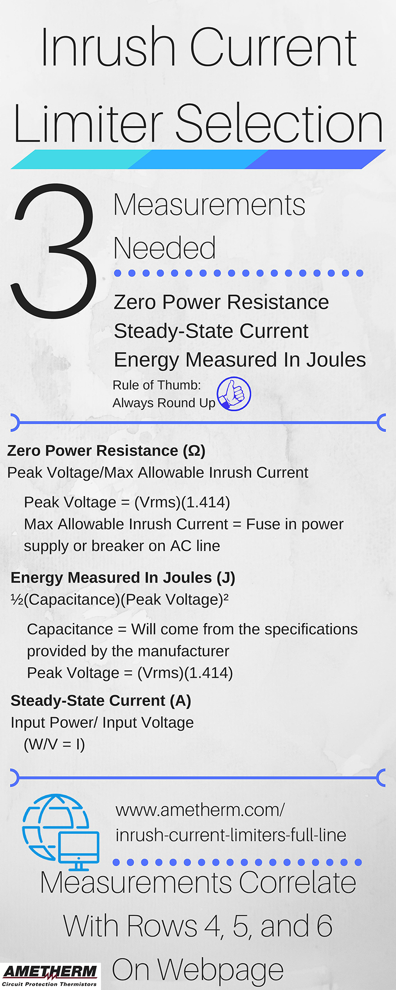
How To Select an Inrush Current Limiter
Choosing the right model of inrush current limiters for your current inrush limiting needs can be vital for any project. Learn how to select the right one.
www.ametherm.com
Is 80A steady-state enough?
Ok makes sense, that was one of my thoughts, the fuse is simply slower than the BMS, and when it was Lead-Acid...the fuse is simply too slow for the in-rush.Fuses have time-current curves.
BMS makes fast current measurement.
Connecting larger inverters, people do blow class-T fuses and weld contactors.
Fuses and lead-acid batteries are nicely dumb things.
Maybe a big honkin' NTC from Ametherm would do the job. Also as dumb as rocks.
How To Select an Inrush Current Limiter
Choosing the right model of inrush current limiters for your current inrush limiting needs can be vital for any project. Learn how to select the right one.
Is 80A steady-state enough?
a NTC Thermistor, if calculated properly, could provide near the same function as the pre-charge circuit and simplify that design so you don't need an additional relay/timer/switch, could be rather smart.
My problem is, I can't find good documentation on what the steady state current on the ZT540e would be (likely somewhat variable dependent on conditions and motor workload?). So I don't know for sure if 80A would be enough. Any time I look up anything on the ZT540e I find much more about its smaller cousins, RM480e, or ZT480ex, which while similar, I would think would have lower in-rush/steady state currents due to having at least 1 less deck motor.
To my original purpose though, for folks wanting to look for any feasible "drop-in" LifePo4 batteries, are there any on the market who's BMS would not trip on start-up and require in-rush protection?
Hedges
I See Electromagnetic Fields!
- Joined
- Mar 28, 2020
- Messages
- 21,080
Unfortunately, I don't think NTC can be paralleled. Needs all its material thermally joined. (PTC, for fuses, I think could be paralleled.)
So you need a big enough one. And by the way they run HOT ?
Some batteries have built-in inrush circuits.
I think some of the Signature Solar server-rack batteries may have.
The issue is whether it meets needs for any given inverter a customer uses it with. External inrush, people can do their own.
But motor likely has less capacitor than big home inverters.
Yeah, noticing that about the NTC.Unfortunately, I don't think NTC can be paralleled. Needs all its material thermally joined. (PTC, for fuses, I think could be paralleled.)
So you need a big enough one. And by the way they run HOT ?
Some batteries have built-in inrush circuits.
I think some of the Signature Solar server-rack batteries may have.
The issue is whether it meets needs for any given inverter a customer uses it with. External inrush, people can do their own.
But motor likely has less capacitor than big home inverters.
The Signature Solar NG4-WP 48V, 100Ah, with its 200A BMS is actually the most surprising to see needing the pre-charge circuit be added...as with its 200A BMS and 350A short circuit safety, I thought it would be more than enough to handle the in-rush...considering we are looking at over ~9600W Steady, and ~16800W short being handled by its BMS.
If I do some quick math (with estimates)...taking 1hp = ~750W, the ZT540e being at most ~8hp we see 6000W this is absolute maximum as that would be at 48V 125A, and risking the fuse.
If we take this, and calculate what *could* be acceptable for the previous lead-acid batteries in short bursts....could the in-rush be roughly 400-550A, 19,200-26,400W?
To add, how are you folks with custom battery packs and external BMS? Do you also need the pre-charge circuit? If not, what BMS is used? Does it have overcurrent/short-circuit protection, and if so, what are the current levels set to trigger them?Yeah, noticing that about the NTC.
The Signature Solar NG4-WP 48V, 100Ah, with its 200A BMS is actually the most surprising to see needing the pre-charge circuit be added...as with its 200A BMS and 350A short circuit safety, I thought it would be more than enough to handle the in-rush...considering we are looking at over ~9600W Steady, and ~16800W short being handled by its BMS.
If I do some quick math (with estimates)...taking 1hp = ~750W, the ZT540e being at most ~8hp we see 6000W this is absolute maximum as that would be at 48V 125A, and risking the fuse.
If we take this, and calculate what *could* be acceptable for the previous lead-acid batteries in short bursts....could the in-rush be roughly 400-550A, 19,200-26,400W?
This info can greatly help us "drop in" folks know what to look for when selecting pre-configured modules.
Hedges
I See Electromagnetic Fields!
- Joined
- Mar 28, 2020
- Messages
- 21,080
100 Ah AGM, someone measured 4000A short-circuit current. You can calculate internal resistance from that, add whatever wire resistance in the mower. That would give peak inrush into a large capacitor bank.
Charging a capacitor from a voltage source, there will be a peak current and tail-off, with integral of I^2R ("R" from the fuse) depositing energy that might melt the fuse.
For BMS, using MOSFET resistance you would get the energy deposited in them. BMS may tolerate some over-current for a brief time. If contactor, it bounces and can weld.
Unless there is some current limit, it is likely to trip a BMS with any good size capacitor.
If going directly to a motor, winding resistance would be high compared to what a capacitor presents.
Mower might power blades directly, but BLDC is popular these days, would likely limit current. Drive wheels would be variable speed, VFD.
Those server rack batteries were meant to power ... servers. They weren't designed for inverter and motor applications. So long as a load does NOT start drawing current immediately, all that would be needed is a time or current based circuit to gradually ramp up gate voltage. Power dissipation in MOSFET could be made arbitrarily low, also deposited energy. But only so long as the load is patient, doesn't turn on.
4000A short circuit for deep cycle!? wow, I wouldn't think the in-rush for this mower comes close to that...but who knows.100 Ah AGM, someone measured 4000A short-circuit current. You can calculate internal resistance from that, add whatever wire resistance in the mower. That would give peak inrush into a large capacitor bank.
Charging a capacitor from a voltage source, there will be a peak current and tail-off, with integral of I^2R ("R" from the fuse) depositing energy that might melt the fuse.
For BMS, using MOSFET resistance you would get the energy deposited in them. BMS may tolerate some over-current for a brief time. If contactor, it bounces and can weld.
Unless there is some current limit, it is likely to trip a BMS with any good size capacitor.
If going directly to a motor, winding resistance would be high compared to what a capacitor presents.
Mower might power blades directly, but BLDC is popular these days, would likely limit current. Drive wheels would be variable speed, VFD.
Those server rack batteries were meant to power ... servers. They weren't designed for inverter and motor applications. So long as a load does NOT start drawing current immediately, all that would be needed is a time or current based circuit to gradually ramp up gate voltage. Power dissipation in MOSFET could be made arbitrarily low, also deposited energy. But only so long as the load is patient, doesn't turn on.
With these mowers motors its ~6 (4x 80V 470uf + 2x 80V 220uf on the deck motor controllers, drive motor controllers are covered) capacitors per motor controller, and in my case, 5 total motor controllers. The in-rush is those ~30 capacitors immediately needing current as soon as the operator turns the key to run and the main relay completes the circuit.
Many drop in LiFePO4 batteries with built-in BMS have 2-3 stage overcurrent protections, the first 1-2 the BMS will operate in for 5-10 seconds, then the last being the full short circuit protection and usually shutting the battery off <0.1ms, we are seeing the in-rush from the capacitors hitting the short circuit protections.
And yes to your last point, that's why the pre-charge circuit works in these cases. What I am trying to figure out, is for anyone who is looking to do a Lithium conversion upon one of these mowers, in the simplest way possible, what would that look like now, so I can explain that to people near me.
Therefore I need to know if going "drop-in" replacement route for LiFePO4, a pre-charge circuit will be fully necessary, alongside a good recommendation to replace the charger, as well as what batteries to recommend.
Last edited:
I think the successful builds that do not require a precharge circuit inadvertantly employed a BMS with automatic reset after a short circuit is detected. My theory is If your BMS requires a dumb charger to reset itself after a short is detected, you will require a precharge bypass or similar. If your BMS auto-resets, it will just work.
Willing to stand corrected here, but would the BMS going into short/reset at all cause the main relay to re-open (due to lack of power to solenoid), shutting the mower off, then close again upon restarting, turning the mower back on?I think the successful builds that do not require a precharge circuit inadvertantly employed a BMS with automatic reset after a short circuit is detected. My theory is If your BMS requires a dumb charger to reset itself after a short is detected, you will require a precharge bypass or similar. If your BMS auto-resets, it will just work.
May not be an issue, but I would think it could be something notable if it does occur.
I think that would depend on the responsiveness of the BMS, right? seems like it would depend on how long until current is reapplied, but I am just speculating based on observations in the thread. Who knows..Willing to stand corrected here, but would the BMS going into short/reset at all cause the main relay to re-open (due to lack of power to solenoid), shutting the mower off, then close again upon restarting, turning the mower back on?
May not be an issue, but I would think it could be something notable if it does occur.
What it doesn't seem to have anything to do with, though, is the rating of the BMS itself, a couple people with 150a+ rating ended up facing the same issue.
Right, solenoid relays are quite quick though.I think that would depend on the responsiveness of the BMS, right? seems like it would depend on how long until current is reapplied, but I am just speculating based on observations in the thread. Who knows..
What it doesn't seem to have anything to do with, though, is the rating of the BMS itself, a couple people with 150a+ rating ended up facing the same issue.
Notably to the second part...in post #696 I believe, @NightStorm is having the issue with the in-rush current with the EG4-WP: https://signaturesolar.com/eg4-wp-lithium-battery-48v-100ah
Which has a BMS at 200A, and short circuit rating of 350A
It's so far been the highest current rated BMS I've seen here, and it still trips.
Another wonder of mine is if you want to avoid DIYing a pre-charge circuit, while going drop in, is if it is going to be worth it. As we could start looking at $2000 and up for LiFePo4 batteries with inbuilt BMS above 500A for short loads
Like this one: Vatrer Power 105ah 200A BMS
Last edited:
I am pretty sure someone also tried a Chins 48v as a drop in, which comes with a 500a peak discharge rating with the same challenges. There's really no telling if that $2000 option would fare any better.
I am leaning towards these myself, if I don't just cave and build my own:
There is a review from 2022 that implies they are drop in, but I am waiting for feedback from @Julie EVD. They took the plunge last week. Hopefully these are a suitable choice.
I am leaning towards these myself, if I don't just cave and build my own:
There is a review from 2022 that implies they are drop in, but I am waiting for feedback from @Julie EVD. They took the plunge last week. Hopefully these are a suitable choice.
Hedges
I See Electromagnetic Fields!
- Joined
- Mar 28, 2020
- Messages
- 21,080
Cover over key switch, and lifting the cover enables precharge?
Precharge enabled by weight on seat?
Key switch has a "key left in ignition" contact, and that enables precharge?
"Insert key and wait until light goes out before starting".
Two-position switch, "Accessories" and "Run". "Turn to first position, wait until light goes out before starting." Same as my diesel.
The Chins 48V from what I read have a 500A short circuit tripI am pretty sure someone also tried a Chins 48v as a drop in, which comes with a 500a peak discharge rating with the same challenges. There's really no telling if that $2000 option would fare any better.
I am leaning towards these myself, if I don't just cave and build my own:
There is a review from 2022 that implies they are drop in, but I am waiting for feedback from @Julie EVD. They took the plunge last week. Hopefully these are a suitable choice.
The Vatrer has a 600A-3 second Overcurrent with 750A short circuit trip.
If you could fab room...there's this beast:
Cloudenergy 48V 150Ah with a 1000A short circuit trip.
The data point I would like to know is just what kind of inrush are we talking?
the more I read the more I am seeing the pre-charge is looking to be almost inevitable...making some YouTube videos like Aging Wheels "easy route" recommendation at the end...a bit misleading.
Do you happen to know the 'short circuit trip' rating on the Overkill BMS? I couldn't find it easily on their website, but I am the quintessential layperson.
I'd be curious to know because that one seems to be unfazed by the issue. I was able to confirm the Overkill is able to reset itself without user intervention after a short, however.
I'd be curious to know because that one seems to be unfazed by the issue. I was able to confirm the Overkill is able to reset itself without user intervention after a short, however.
It's programmable to my knowledge, which is why I was trying to ask any folks who used it what they may have set it to, if that is the case...Do you happen to know the 'short circuit trip' rating on the Overkill BMS? I couldn't find it easily on their website, but I am the quintessential layperson.
I'd be curious to know because that one seems to be unfazed by the issue. I was able to confirm the Overkill is able to reset itself without user intervention after a short, however.
@AMDPower did you use the overkill BMS?
So after doing estimation math for too long, and consulting a eentsy bit of AI to scour the web for the specs of Ryobi's motors and motor controllers.
Given AI's ability to make up facts, take all following with doctors recommended doses of salt.
The estimated inrush current I have is 370-400A
Given this;
BLUF: Any LiFePo4 battery package with at least peak amperage of >400A should be good to "drop in" without a pre-charge circuit
The CHINS 48V 100ah Battery should be specced Ok to drop in WITHOUT a pre charge circuit, but at 500A peak, it is close, and this is reliant on some speculation both due to possible AI shenanigans, and inconsistent marketing from CHINS:
On Amazon: Peak Amps "500A"
On CHINS website: Peak Amps "300A"???
The Vatrer 48V 105ah Battery is well above what's needed to run at 700A [correction 600A-for 3 Seconds, 700A was a Typo] peak with no pre charge circuit, and may just be a "safe" bet, less reliant on speculation due to a higher buffer.
[Correction 2, Some inconsistent marketing with Vatrer exists, as their website does not have the 600A spec, only the amazon listing does, Thanks @MowerConversion for the catch!]
All Ampere/Li Time package BMSs that I have seen have 250-300A peak current and will require a pre-charge circuit
The EG4 48V 200A battery short circuits at 350A, just below 370A, and needs a pre-charge circuit
Last edited:
I'm in my 4th season with a 42" Ryobi ZTR (100AmpHr). Since purchase I've observed an "in house" rule of stopping mowing at or before 50% depth of discharge. Battery life and mowing time was fine thru the first three seasons of use. Now in the 4th season, I'm getting only 20 minutes or so of mowing run time when I reach 50%. So the research has begun regarding how to convert to Lithium. I'm leaning toward a single 48V, 96AH battery, new (matching, for lithium) charger and new charge indicator. I'd rather not "fiddle" with four 12V batteries and balancing - hence the single 48V battery intention. I've been reading with great interest about "pre-charging" the capacitors. I'm going to have to learn fast - the old SLA's are nearing end of useful life.I just snagged a ZT480ex from a local outlet store, factory reconditioned, for $2k. Had 8 hours on it, comes with a 1 year warranty and 30 day return policy, I think it was a pretty decent deal. I know a little about LFP batteries from a small solar setup I built. Immediately thought I could shove one in this thing when the SLA batteries die. Going to bookmark this thread, I'm almost excited for them to die to try and retro fit it! Anyone have any experience how long the stock batteries last? Guessing 2-3 years before it gets noticeable? I'm mowing a little less than 2 acres, probably around 20 times a year. I was reluctant to get it with lead acid batteries and some unfavorable reviews regarding it's longevity, but figured I would give it a shot. I'm already exhausted dealing with my old Cub Cadet's deck problems, worst case I have 2 half working mowers in a few years.
Similar threads
- Replies
- 7
- Views
- 607
- Replies
- 3
- Views
- 1K
- Replies
- 1
- Views
- 406
- Replies
- 4
- Views
- 196
- Replies
- 26
- Views
- 7K