diy solar

diy solar

Ryobi Zero-Turn Mower SLA to LiFePo4 Conversion - (Updated - Build Complete With Pics!)

After 3 seasons my original SLA batteries on my RY48ZTR75 75 Ah pack started giving up the ghost. This thread, which I've been scanning for a while, has been invaluable in pulling off a replacement. After reading I decided on a couple of main factors in deciding on a replacement battery:

1. A full 48V unit to simplify replacement.
2. A battery with customer service backup I felt I could trust.

I couldn't find anything on Amazon that actually gave me a good feeling on #2. It's one thing returning and shipping back a pair of shoes. But on a battery that runs up to $1500 is a whole nother level.

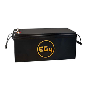
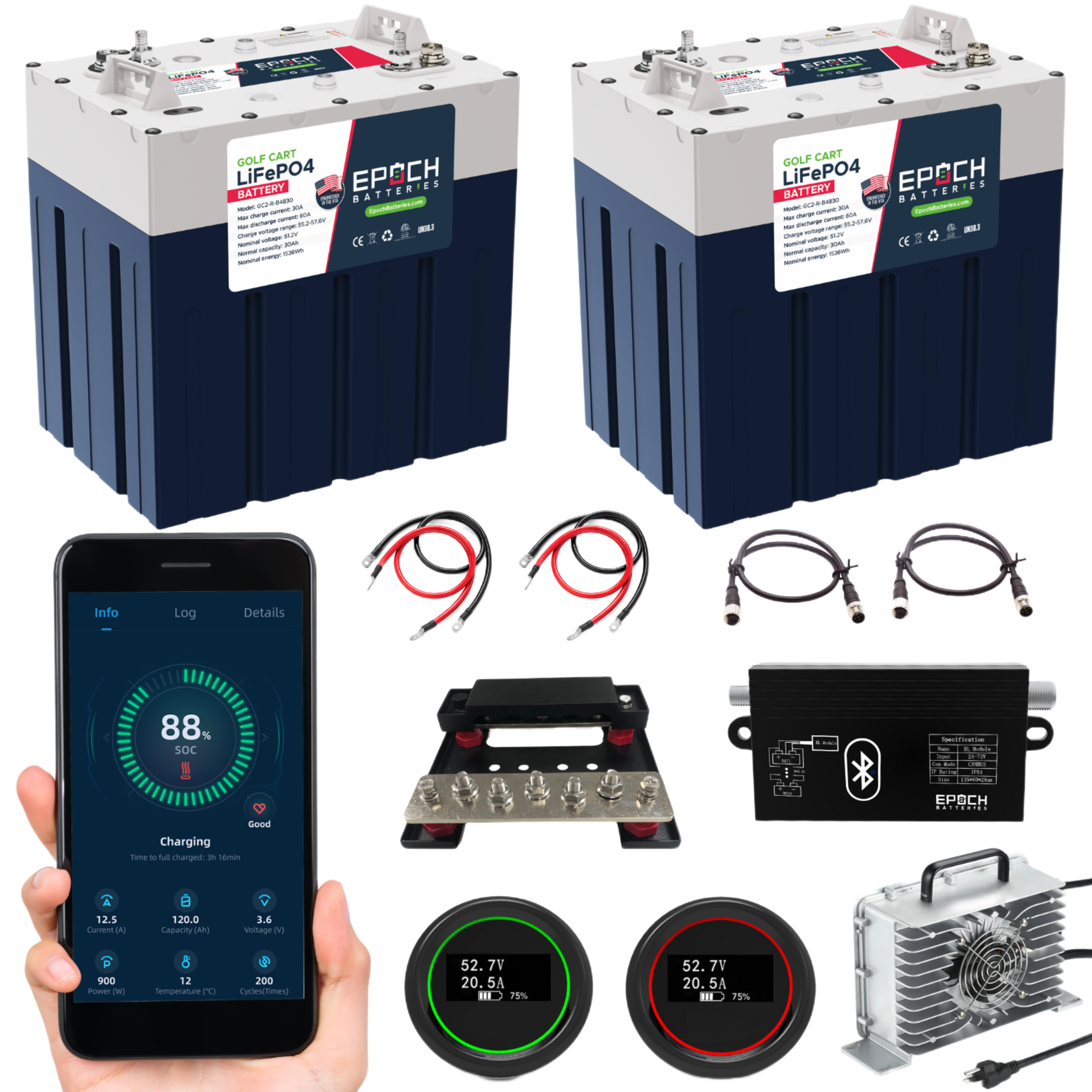
I finally found a niche searching for 48V Lithium Golf Cart Batteries. I finally settled on this 48V 60 Ah Golf cart kit:


I'm aware that I overpaid for the capacity I ended up getting. However, their distributor is in the local Atlanta area, so I was able to drive to the warehouse and pick up the kit. It was the only option I could find that met requirement #2 for me.

I had to do a bit of adjustment to get everything to fit. At 10.7 inches high, the battery modules were too tall to fit upright. I ended up turning both sideways with terminals facing the center of the tray. I also had to adjust the end brackets so they would fit with enough separation for the wiring.

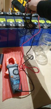
I wired everything back except for the additional BAT+ connector that routes somewhere to the original charging port. It fired up on the first try.

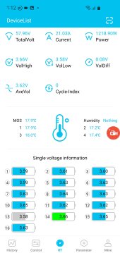
It's interesting to see the combined BMS of the two units operate. Once the battery gets low there is a hard cutoff. Then after 45 seconds or so, the battery recovers, the BMS kicks back in, and the contactor on the lawn mower starts clicking. It'll then operate for a short amount of time before cycling. But I was able to drive it from the back yard back to the carport.

Getting the charger with the kit made charging simple. I just plugged it in and let it go. It cut off with a full charge on its own. I unplugged it anyway just in case.

I was able to cut an almost full 1 acre of tall tough grass before it cut off. And I'm pretty sure the batteries were not fully charged out of the box.

When I get a chance I'll follow up with pictures. Also I have to figure out how to integrate the meter that came with the kit to the mower. Also I know I'm going to need to add some spacers between and around the battery modules to ensure they stay in place on the tray.

But all in all I'd call this a successful replacement that only took a weekend to get done.

ga2500ev
 
Hey all, awesome thread and tons of great info. I just placed my order for 16 100ah cells and an overkill BMS. I've had a ryobi rm480e since 2019. It worked great for the 1/3 acre flat yard we had. But I got a new job and we moved to an area where grass grows 2x as much have an acre yard with 12 degree slope. Needless to say the batteries are finally dying. Time to upgrade. Will post more once I get started. Thanks in advance to all those who paved the way!
 
Hello everyone - I did the 105Ah LiFePO conversion of my RM480e back in July and the results were fantastic. I went from being able to barely finish my 1/2 acre yard on a charge to getting 4 mows per charge.

However, I’ve recently run into a problem with the drive system. My mower now will usually not move unless I get a push to get going. Then if it does go, it has less power and throttle response and sounds like it’s struggling. The motor coils ohm out the same and the hall sensors all vary in voltage between 0 and 5v when turning the motor. The blades engage without an issue, so it doesn’t seem to be a battery issue.

Has anyone else run into this? It seems to point toward a bad drive motor controller, which is a spendy part. Does anyone have any troubleshooting steps specifically for the RM480e? I found a document for the zero-turn version.
I haven't posted in a while, but I wanted to give an update on this issue. The drive motor controller was actually bad, and after replacing it I found that it may have been bad from the start. Reverse had always been all-or-nothing, with no variability in speed. Now with the new drive motor controller reverse has a slower max speed, but the speed is variable. Maybe this was a symptom of a defect, maybe the new drive motor controller is a different revision.

Regardless, the after swapping the drive motor controller out I'm back to mowing.

For those who are wondering, I found the new OEM drive motor controller from a seller on eBay for about $300.
My overkill arrived today, still waiting on batteries. The symptom you described of reverse only being 1 speed and being max speed sounds like my machine. Always thought it was a design flaw, but maybe it is controller issue. Guess I will let you know how mine reacts when I test my new battery setup.
 
Like many others, I joined this forum as a result of this thread (via a link on a Home Depot review). I just started a third season of mowing with my Ryobi 75AH ZTF mower and it only did 1/2 the lawn. With two more charges it finished the mow and subsequently got worse. I can now get 5, maybe 10 minutes of mowing. The meter transitions from 100% to 95%, I then hear the mower deck slow, and then total shutoff. Looks like it is time for me to look into the LiFEPO4 route.

While I do have the skills to do the whole DIY route with cells, BMS, etc. a lack of time and energy is steering me toward "laz-ing out" and just getting something like the Chins 51.2v unit. The fact that I don't have to deal with building a box, figuring out what to do for a meter (I'd just use the Bluetooth connectivity), wiring the BMS and all means that yes, I'll spend more $$ but I can more quickly resume the battle with the sprouting dandelions. Plus this particular unit has cold temp. cut-off which (I think?) means I can leave it plugged in in the shed during the winter as I had been doing for the existing lead-acid pack.

I read this whole thread, I believe I saw comments that one can use the existing lead-acid Ryobi charger because the BMS does the right thing. If I remember that correctly, is anyone actually doing that or is it really necessary to invest in a new charger?
 
For just a few bucks more, you could buy this 48V SS battery and have 2x the BMS output.
Seems like a better bang for the buck.

I revived a RM480e that the previous owner thought was dead.
I pulled apart the battery bank and charged the individual batteries until they all held almost a full charge, then wired them back together and put them on the DeltaQ charger that comes with the mower.
I have the charger plugged into a smart switch that power cycles the charger every morning and forces a charging cycle. So far it's working far better than expected and when these batteries finally die, I'm planning to replace with the Sig Solar battery I linked to above.
Thanks, but the link did not make it to the press.

Edit: I suspect you meant this. ;)
 
Last edited:
Yeah, that is the one. 100ah battery with a 200amp BMS
Thanks for the reference, nice unit. Sadly their website is not cooperating on telling me the shipping charge so I cannot yet see just how many more dollars it is.

Also it may not fit. I notice that it is taller than the Chins at 9.125" (and I don't know how much the posts on top would add). I have not taken my mower apart to see what the exact measurements are but in post #39 AMDPower says about 8.5" in height. Will have to wait for the weekend.

Edit: Just took the back mower skirts off and measured .. looks like it will fit. Also called them to make sure it has low temp. cut-off (it does), so it is now ordered. ;)

What is a good charger to get? Do the chargers also do low-temp cut-off? Probably nice to have a backup on that functionality given that the mower sits in an unheated shed during the winter (and it gets sub-zero here).
 
Last edited:
IMG_7427.jpegIMG_7426.jpegIMG_7429.jpegIMG_7417.jpeg
Just completed my conversion. A note on the pre-charge circuit: I was having the issue of bms tripping out on the initial key turn from in rush current (solenoid would just continuously click and never engage). I was using the 150amp Daly bms. In an attempt to solve the problem without having to add anymore circuits, I swapped to a 200amp bms and the problem stopped.
 
I've been paralleling on a bench charger for days after a full series charge... Quick question: Is this pack balanced or unbalanced? Is it time to build the battery or should I keep balancing?
 

Attachments

  • Screenshot_20230604_131253_XiaoXiangElectric.jpg
    Screenshot_20230604_131253_XiaoXiangElectric.jpg
    163.3 KB · Views: 11
It is still drawing 21A, but one cell has reached 3.66V
I think people normally stop at 3.65V to avoid over-charge, then charge the remaining cells up to same voltage.
That topping off is often done with all cells in parallel, but can leave cells in series and charge one at a time.

57.96V / 16 cells = 3.6225 per cell

Cell 13 is lowest at 3.58V, cell 14 highest at 3.66V

At what cell voltage is BMS set to disconnect? At what maximum pack voltage is charger set?

You aren't Balancing" at this point, you're series charging.
You could stop now and balance. If connected in parallel, you could parallel top-balance to 3.65V. Or individually charge to 3.65V.
You could bleed charge off highest cell 14 with a resistor until it is down to the others, could charge lowest cell 13 until it is up to the others.

You could just call it good enough and adjust charger voltage so it stops a bit lower than this, let BMS gradually balance further.

I think it would be nice to get well balanced at 3.65V/cell once and then operate a bit lower, but depends on the equipment you have (a 3.65V CV/CC supply?)
 
Thanks @Hedges, I know I'm in safe hands following your sagely advice.

The charger I'm using (link below) says it charges with a constant voltage charge of 58.4V, which is exactly 3.65 per cell, which I think means they need to be perfectly balanced in order not to overcharge something. Seems like a riskily high setting, but I don't think I can change this - so I suppose that answers the question of whether I need to keep balancing.

That however seems problematic. I'm new to using a CV/CC bench charger (link below), but so far it's been in parallel for four days, after doing the full series charge shown in the screenshot of the previous post. The cell voltage settled to around 3.30V after the series charge, and is now around 3.35V. The bench charger is currently putting in around 2.8A. That's an increase of 0.05V after four days. And the nearer I come to my target voltage the lower the amps get. I did a test yesterday and couldn't even raise a single cell from 3.35 to 3.36 in an afternoon, because I was getting a measly 0.1A. I just don't see how I'm going to charge the 16x 160ah cells from 3.35 to 3.65 in a month of Sundays.

Perhaps I'm not understanding something. I hope so. I might try your resistor trick; perhaps I'll have more luck discharging than charging.

Regarding the BMS's overcharge cut-off value, I'm not sure, it doesn't seem to have one. I have a JBD bms and am monitoring it through their own Xaioxang (Little Elephant) app. I was expecting it to cut off at 3.65 but I let it go a little higher to test it and eventually pulled the charger plug myself at 3.68. (It had fallen back to 3.66 by the time I took the screenshot) There is nowhere I can see, or set, parameters on the app, but I thought it should have a protection cut-off built-in such that it would cut-off even without installing an app.

I'll perhaps try a different app, perhaps the Overkill Solar app, but I still don't understand why the bms wouldn't protect the cells from overvoltage itself.

Anyway, thanks very much for your response.


Attachments

  • 20230604_175800.jpg
    20230604_175800.jpg
    127.1 KB · Views: 8
  • 20230604_175725.jpg
    20230604_175725.jpg
    332.9 KB · Views: 8
*REVISED*

I'm still struggling a bit with the whole pre-charge circuit thing. I took the side cover off the mower to access where the primary contactor is located.

I have read a lot of information in regards to pre-charge circuits using contactors and such for EV vehicles which use much higher voltage battery packs and capacitors, but technically the problem still exists for these Ryobi mowers which is why my battery BMS seems to trip due to the inrush current when the motor capacitors have drained.

It seems to be fairly straightforward to install a 48v rated DC momentary switch with a resistor across the existing solenoid/contactor, hold down the momentary switch for a period of time, then turn the mower key switch to 'ON' to activate the contactor. While that appears to be a simple approach, I didn't like the idea of requiring a procedure to pre-charge the mower. Also, there is nothing to prevent someone from forgetting a step and just turning the mower key on without holding the "pre-charge" momentary switch resulting in tripping the BMS. I have been trying to figure out a more elegant solution.

I wanted to stick with the existing mower single key to turn the mower on without the need to remember to pre-charge. After doing some research it looks like a Single Pull Double Throw (SPDT) multi-function timer relay would do the trick for the timing part. If I set the timing option to a non-signaled ON-DELAY where the default switch path directed to the pre-charge circuit.

The idea is that while the mower key is in the OFF position nothing runs since the entire mower circuit is open. The SPDT timer relay is in the default position that would by default send its current through a pre-charge circuit which is just the resistor connected to the output side of the contactor. When you turn the starter key to the ON position it would close the main circuit while using the switch path for the pre-charge circuit. After a configurable time (say 5-10 seconds) the timer relay would energize and automatically switch to the activate the primary current path through the contactor. When you turn the mower key off it resets everything back to the default state.

The only caveat is that you would need to remember that there is a x-second delay until the current is switched over to the primary contactor from the timer relay. I'm thinking of adding a couple of small LED lights, one to each switch path from the timer relay, where the led light is RED when the pre-charge circuit is active and then it will turn off and activate a GREEN led on the main contactor path when the timer relay switches to the that circuit path.

I was also considering moving the battery meter/shunt Bpos wire from the battery terminal, which always causes the meter to be on, to the outbound connector of the contactor so that the monitor would only turn on only when the mower is turned on and avoid the trickle drain on the battery.

When I originally posted I was trying to avoid another switch beyond just using the timer relay plus resistor as the path for the pre-charge circuit. However, I got concerned that the timer relay coil contact switch wasn't actually rated for 48v. So I decided it was probably safer to just get another 48v ClubCar solenoid/contactor that is rated for 48v DC with an additional resistor to use for the precharge circuit. Then I adjusted the wiring for the timer relay from using the wires from the 48v switch to hooking onto the 12v wires that are used to signal the primary contactor/solenoid. It seemed to be the safest approach and keeping everything within the DC voltage specs of each component. It also allows you to just use the key to turn on the mower without any other steps than waiting a few seconds for the pre-charge to complete automatically.

I updated my original pre-charge circuit design to the attached image. I would be curious what the group thinks about this approach.

I figured worse case it doesn't work, I pick up a 48v DC momentary switch and just install that which would be the most simple. I was also struggling a bit with how to mount another contactor/solenoid for the pre-charge, the timer relay, and the pre-charge resistor. My working theory is to use an 8" slotted stainless steel mender "sandwiched" between the original contactor and its mounting bracket. Then I can mount the pre-charge solenoid to the extended part of that mender. The slots give me flexibility to shift things around. I'm thinking of using a few other strips of the slotted menders to act as "hangers" off the horizontal mender so that I can mount the timer relay and pre-charge resistor below the pre-charge solenoid/contactor. This should give me some flexibility to shift things around without trying to fabricate a mounting plate of some kind.

I'm going to try to test this out when I get all the parts in this week. If it works, I'll post final pictures.
I used the EG4 WP 48V 100AH (with the new 200 amp bms) and had the same issue on the initial key turn. The main relay would 'chatter' and the battery would go into protect mode. I got an adjustable time delay relay with a 12v coil and another larger relay also with a 12v coil. Smaller relay turns on the larger pre-charge circuit relay (using the NC contact) which charges the capacitors through a power resistor, then after the delay the same small relay (now using the NO contact) disconnects the pre-charge circuit and energizes the original main relay. Works great! I probably will turn the delay down a bit (currently set for around 5 seconds). I did also put a flyback diode on the larger pre-charge relay, just like the original.

I liked your idea for the pre-charge circuit with a TDR. I wanted something that would allow anyone to jump on the mower, turn the key, and go.
 
Thanks for the reference, nice unit. Sadly their website is not cooperating on telling me the shipping charge so I cannot yet see just how many more dollars it is.

Also it may not fit. I notice that it is taller than the Chins at 9.125" (and I don't know how much the posts on top would add). I have not taken my mower apart to see what the exact measurements are but in post #39 AMDPower says about 8.5" in height. Will have to wait for the weekend.

Edit: Just took the back mower skirts off and measured .. looks like it will fit. Also called them to make sure it has low temp. cut-off (it does), so it is now ordered. ;)

What is a good charger to get? Do the chargers also do low-temp cut-off? Probably nice to have a backup on that functionality given that the mower sits in an unheated shed during the winter (and it gets sub-zero here).
I did my conversion with this exact battery. It fits perfectly without any modification. I added some dense foam to the sides of the battery tray to lock the battery in and a pull strap over the top to the frame to hold it down (though it's nice and snug in the foam with the battery tray clamps, probably didn't need a strap). I will also say that you need a pre-charge circuit as the BMS will trip on the initial key turn due to the inrush.
 
I did my conversion with this exact battery. It fits perfectly without any modification. I added some dense foam to the sides of the battery tray to lock the battery in and a pull strap over the top to the frame to hold it down (though it's nice and snug in the foam with the battery tray clamps, probably didn't need a strap). I will also say that you need a pre-charge circuit as the BMS will trip on the initial key turn due to the inrush.
I just got mine today and installed it. Easy-peasy. Used some Gorilla tape and a double layer of cellular PVC trim. Let's see how long before I regret that bad decision. ;). Like others it won't "start" due to the need of a bypass so later this I am week I am going to try a quickie time-delay circuit for the bypass using a 12v auto relay, cap, and a couple resistors. We shall see.

In the meantime ..

The Arrival:

TheBattery.jpg


The Tape & Cellular PVC:

TheTape.jpg


Ready to slide in:

ReadyToSlideIntoPlace.jpg
 
Last edited:
I just got mine today and installed it. Easy-peasy. Used some Gorilla tape and a double layer of cellular PVC trim. Let's see how long before I regret that bad decision. ;). Like others it won't "start" due to the need of a bypass so later this I am week I am going to try a quickie time-delay circuit for the bypass using a 12v auto relay, cap, and a couple resistors. We shall see.

In the meantime ..

The Arrival:

View attachment 151849


The Tape & Cellular PVC:

View attachment 151850


Ready to slide in:

View attachment 151852
Looks like your battery has the new COM port on it. Supposedly it allows communication with the BMS. Mine first battery got locked in protect mode and they had to replace it since there is no way to access the battery without cutting into the case. Did your battery come with any literature regarding that port?
 
Back
Top