diy solar

diy solar

Safe Grid Use of the 5000ES and transformer

Everyone should do their own research and decide what is the best fit for their needs. And if they have the skills to implement it safely. This is what makes the information in these conversations so valuable.
We are all here to learn and help educate others.
I for one, am happy to be a part of the community growth.
 
Using a quality isolation transformer makes the 5000ES not such a great deal. Other split phase inverters (LV6048) are available for $250 USD more than the single 5000ES with autotransformer.
I agree.
It all depends on the individuals situation.
I have shelves full of "free" spare equipment.
And, the skills to design and build a safe and efficient system.
So for me, this is a very cost effective solution.
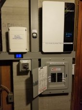
My current setup, which is still evolving.
 

Attachments

  • 20220209_195959.jpg
    20220209_195959.jpg
    122.6 KB · Views: 70
Last edited:
To most true DIY persons the risks are acceptable
#speechless
The ones that do get injured,... well maybe the world will be a little safer without them me included.
#morespeechless
Your interpretations may be judged differently if brought to a court
what does that even mean?!

IMHO- fortunately these sentiments are not broadly distributed in the populations.

A product that can kill either from poor design or ignorance of the installer or both probably shouldn’t even be sold in North America due to the fact that most diy people- including myself to a point- are ignorant of the mystical behavior of transforming 240 to neutral/split phased 120V. Following flawed instructions lets people install stuff unaware of the risk. Being ignorant of the risks doesn’t make the risk(s) acceptable. An ostrich approach if done willingly is incomprehensible when safe solutions are at hand.
I’m watching, expecting SS to eventually provide the drawings and documentation for running these machines safely. Because apparently, the risks are not acceptable to them either.
 
Electrical safety, should never be compromised. Because, it's impossible to know who will come into contact with the system. Including the neighbors kid, who decided to charge their phone from your outside outlet on their way home.
 
#speechless

#morespeechless

what does that even mean?!

IMHO- fortunately these sentiments are not broadly distributed in the populations.

A product that can kill either from poor design or ignorance of the installer or both probably shouldn’t even be sold in North America due to the fact that most diy people- including myself to a point- are ignorant of the mystical behavior of transforming 240 to neutral/split phased 120V. Following flawed instructions lets people install stuff unaware of the risk. Being ignorant of the risks doesn’t make the risk(s) acceptable. An ostrich approach if done willingly is incomprehensible when safe solutions are at hand.
I’m watching, expecting SS to eventually provide the drawings and documentation for running these machines safely. Because apparently, the risks are not acceptable to them either.
Yeah I did not reply because I realized he has no idea what he is dealing with. He thinks this is some sort of Go Kart build where you go down the hill and if bad things happen it only happens to you. He has no idea that three quarters of the people on this forum have wives and kids and it's the kids that are more than likely going to pay the price for a DIY screw up. Even now he will say I am using a scare tactic because he will never understand the dangers of messing with electricity until something bad happens to him or someone close to him.
 
Chinese New year has been done for over two weeks, has Growatt said anything about a safe wiring diagram for Split Phase usage of the 5000 Series? The last Diagram had two separate grounds plus other issues.
 
I solved my issues with the 5000.
Was going to post it, but haven't had time to put it all together. Basically, run a neutral from the main panel to the sub panel. This gives you a n/g bond. And put a relay on the auto transformer, so that it's not connected when grid is connected. This keeps it from paralleling with the grids transformer.
Do you have a diagram we could see? Others with the issue would appreciate it.
 
I'll post it up this weekend. When I get time to put everything together.
 
It's currently just in my head. And my tablet isn't sophisticated enough to upload my thoughts. lol
Give it time, we are getting there, just make sure your wife doesnt share the same iBrain account :p
 
I very recently purchased (still in the boxes) the SPF 5000es USA model and the growatt At-5000 transformer from signature solar as a package deal. My intention was to use the AC input function, as outlined in the manual, along with solar and battery and send the AC output to a generator transfer switch already wired in my home, specifically one of those Reliance Controls transfer switches that have each individual circuit on its own switch. This would allow me to flip the switches and completely bypass the growatt system and place my circuits strictly on the grid if need be The neutral wires in the transfer switches are stationary, with only the hot wires being a part of the switching process. After finding this forum and doing a fair bit of reading, it sound like the inverter and transformer might not be a great option in my application due to the neutral bonding issue between grid neutral and the auto-transformer neutral. Had I known about this prior to purchase I would have probably opted for 2 of the SPF 3000TL LVM-ES.

Does anyone know of a safe and practical way to utilize the 5000es while having the the grid neutral and transformer neutral bonded?

Also on another note, I noticed the Growatt-america website placed an updated manual on there website called SPF US Series User Manual V1.0 2022 but its missing the .pdf at the end of the file name. After putting the .pdf at the end of the file and opening it up, I noticed they updated the manual to show the US version.
 
The problem isn't that they are both bonded. (As long as the only N/G bond is at the main panel)
The problem is that the auto transformer shouldn't be connected at the same time as the grid, to the same loads. If you don't connected the grid to the inverter input. There shouldn't be an issue. (As long as the auto transformer is connected between the inverter output and the transfer panel.
 
That's what I thought. I had planned to connect the grid to the inverter input and use it through the auto transformer. I didn't realize the neutral wires had to be separate before I purchased. I am planning to use the generator transfer switch because it is already wired and has the appropriately sized wires. My homes ground and neutral are bonded in the main panel outside of my home, directly under my electric meter. The transfer switch is located inside my home next to my inside load panel (neutral and ground are separated in this panel. The neutral wires of my individual circuits are connected to the neutral bus of my inside main panel while the hot wires of each circuit pass through the transfer switches. The 3000w models pass the neutral through and tie in to the grid neutral eliminating my issue, hopefully signature solar will let me return the 5000es/AT-5000 package and pickup a couple of the 3000w models.
 
That's what I thought. I had planned to connect the grid to the inverter input and use it through the auto transformer. I didn't realize the neutral wires had to be separate before I purchased. I am planning to use the generator transfer switch because it is already wired and has the appropriately sized wires. My homes ground and neutral are bonded in the main panel outside of my home, directly under my electric meter. The transfer switch is located inside my home next to my inside load panel (neutral and ground are separated in this panel. The neutral wires of my individual circuits are connected to the neutral bus of my inside main panel while the hot wires of each circuit pass through the transfer switches. The 3000w models pass the neutral through and tie in to the grid neutral eliminating my issue, hopefully signature solar will let me return the 5000es/AT-5000 package and pickup a couple of the 3000w models.
Hopefully, they will.
And if they can offer me a small discount, I'll take it off of their hands. lol
I'll be needing another, soon.
They can ship it with my next battery order.
 
Greetings,

I just ran across this forum today, and hope someone can provide feedback. Attached is a diagram of how I thought I should do this, I'm open to suggestions. In summary, I plan(ed) to swing most of my house load over to 3 new sub panels by moving the wire and breakers. The 3 panels would be "house critical", "house non-critical", "barns". These would be main lug panels feed by 3 transfer switches which switch L1-N-L2 lines. One feed would be from a breaker in the original house panel, the other feed from the output of a Growatt autotransformer. The autotransformer would have 2P 20A breaker between it and the SPF5000ES. The output of the transformer would connect to the 3 transfer switches through an over/under voltage breaker. The 5000ES AC input L&N would be connected to another breaker in the original house panel, to allow for battery top off and bypass as needed. In the house panel, earth ground is bonded to Neutral, it would not be bonded in the sub panels. Earth ground would also be connected to 5000ES and the autotransformer case. Btw, the 5000ES is the US model. I'm thinking, per reading many of the forum posts, this will be ok. as the Neutral in the sub panel is always switched along with the L1/L2 depending on the chosen source. Except, I'm think the earth ground for the 5000ES and autotransformer need to go to a separate grounding rod since the ground and neutral are bonded at the main house panel. Thanks in advance to your thoughts!!
 

Attachments

  • 5369_rewire.PDF
    720.4 KB · Views: 32
Greetings,

I just ran across this forum today, and hope someone can provide feedback. Attached is a diagram of how I thought I should do this, I'm open to suggestions. In summary, I plan(ed) to swing most of my house load over to 3 new sub panels by moving the wire and breakers. The 3 panels would be "house critical", "house non-critical", "barns". These would be main lug panels feed by 3 transfer switches which switch L1-N-L2 lines. One feed would be from a breaker in the original house panel, the other feed from the output of a Growatt autotransformer. The autotransformer would have 2P 20A breaker between it and the SPF5000ES. The output of the transformer would connect to the 3 transfer switches through an over/under voltage breaker. The 5000ES AC input L&N would be connected to another breaker in the original house panel, to allow for battery top off and bypass as needed. In the house panel, earth ground is bonded to Neutral, it would not be bonded in the sub panels. Earth ground would also be connected to 5000ES and the autotransformer case. Btw, the 5000ES is the US model. I'm thinking, per reading many of the forum posts, this will be ok. as the Neutral in the sub panel is always switched along with the L1/L2 depending on the chosen source. Except, I'm think the earth ground for the 5000ES and autotransformer need to go to a separate grounding rod since the ground and neutral are bonded at the main house panel. Thanks in advance to your thoughts!!
Don't install a second ground rod.
Everything in the system should get its ground from the main panel.
The transfer switches need a 4th pole. This is used to bond the neutral to ground.
"Next comes the tricky part "
In bypass mode, this creates a ground loop. And possible current flowing on the ground conductor.
The best solution for this is to add a relay to disconnect the neutral/ ground bond, and connect a bypass neutral, when the inverter feed breaker is turned on.
And, keep this breaker off when not needed.

So.......
Your neutral/ ground bonding (green 12 gauge) wire and bypass neutral (white appropriatly sized) wire, would go to the relay. (Which would choose which is feed to the transfer switches 4th pole) from the relay, run a white appropriately sized wire to the transfer switches. (4th pole)
Then connect (with an appropriately sized white wire) the output of the 4th pole to the neutral output.

The purpose of this is to provide a neutral from the main panel in bypass mode. And provide a neutral/ ground bond when not in bypass mode.

The last remaining issue is that when in bypass mode, the auto transformer is put in parallel with the grid split-phase transformer.
This is why you should keep the breaker that feeds the inverter off, when not needed.

Hopefully, I made this easy to understand.
 
Sorry, that's an old rough draft.
And, I haven't figured out how to delete a post.
So, I'll just leave it for an interesting read.

Simpler solution:
Transfer switches only switch the hots.
Keep inverter feed breaker off, when not needed.
 
In the manual it shows 50 amp Breakers for the AC in. What size breaker do I need for the AC out. The transfer switch diagram shows 20 amp. I have three inverters 5000es-us. I will be running them in parallel. I will not be using the transfer switch as I have separate panels for solar and AC each having their own neutral and ground. 20 amp breaker for the AC out panel does not sound correct. Sorry to tag onto your post seems like you have a nice set-up going.
 
I have three of these inverters from SS, six of the batteries and 1 transformer. I will be grounding my solar setup separate. I will then run ac out panel L1 L2 wiring to my main 200-amp breaker in my house panel. The 200 amp breaker will be a means of disconnect. I'm going to remove existing grid/utility L1 L2 neutral and ground from this Main panel.
My neutral from my Transformer of course will be my new neutral in this house panel. The new ground in this will be the ground from the solar system ground rod.
Now I'm going to run L1 L2 neutral and ground wires from the grid into a new 200amp panel with main breaker next to my house panel. The new panel will contain 3 double pole single throw Breakers. L1 and L2 from each one of these Breakers will be powering an inverter.
This separates grid power from solar power. It also provides grid power to the inverters. I spoke to Signature solar tech team. They do not have an updated drawing of the 5000 ES Split Phase Grid Connection (with Bypass Switch).
Basically It was a no-brainer for my situation.
 
This separates grid power from solar power.
Not when those breakers are on.
The new ground in this will be the ground from the solar system ground rod.
This creates a ground loop, when in bypass mode.
And a parallel connection (through the earth), between the auto transformer and the grids transformer.
Using an auto transformer is what creates all of these issues.
Now you will have current flowing through your yard, looking for an easier path. (Like bare foot children , or pets)
 
Last edited:

diy solar

diy solar
Back
Top