Why? taking only L1 and L2 from grid is like use the L1 and L2 on the inverter, in others words there will be no unbalance.That's a major issue for bypass mode.
All of the unbalanced load is going to be on the ground conductor.


You are using an out of date browser. It may not display this or other websites correctly.
You should upgrade or use an alternative browser.
You should upgrade or use an alternative browser.
Safe Grid Use of the 5000ES and transformer
- Thread starter SignatureSolarJames
- Start date
JohnGalt1717
New Member
- Joined
- Dec 22, 2021
- Messages
- 107
(Well there is if there is an unbalance on the 2 legs of 120V created by the auto-transformer, but that's literally why you have the auto-transformer, to balance that out. So as long as you have excess over max unbalance, it is designed to handle it, and if you don't, then you're going to blow up all of your 120V stuff if the breaker on it pops, which we knew. That's why you overside your auto-transformer and by virtue of how electricity works, you'll only experience loss of having a second one hooked up if it's actually in active use. Otherwise it's balanced and thus no electricity flowing through it.Why? taking only L1 and L2 from grid is like use the L1 and L2 on the inverter, in others words there will be no unbalance.
You don't need do that if you connect the inverter directly to the autotransformer, if the breaker pops it will cut the inverter and the autotransformer at the same time...(Well there is if there is an unbalance on the 2 legs of 120V created by the auto-transformer, but that's literally why you have the auto-transformer, to balance that out. So as long as you have excess over max unbalance, it is designed to handle it, and if you don't, then you're going to blow up all of your 120V stuff if the breaker on it pops, which we knew. That's why you overside your auto-transformer and by virtue of how electricity works, you'll only experience loss of having a second one hooked up if it's actually in active use. Otherwise it's balanced and thus no electricity flowing through it.

Attachments
JohnGalt1717
New Member
- Joined
- Dec 22, 2021
- Messages
- 107
Yup, that's for the new one and that also implies that you have one auto-transformer per inverter which I don't, because I have a max 5000W imbalance (measured with extensive testing) on the 120V yet I routinely use 27kW of power while charging our car and running our heat pump and the dryer on and the dishwasher and hot water running.You don't need do that if you connect the inverter directly to the autotransformer, if the breaker pops it will cut the inverter and the autotransformer at the same time...
So I have 6 inverters with 6 strings of solar, and 2 auto-transformers, of which one of them virtually never has any amperage on it at all. (I've yet to ever drive more than 5.1kW of total 120V and that was just in testing, normally it's under 1.5kW)
If I was to do it again, I'd use EG4s or switch to one of the new 96V inverter/solar charge controllers that do native split phase, but I don't have that kind of money, so I've just made sure I have enough capacity at the cost of a slight power wastage in all circumstances.
The second autotransformer don't need to be connected in that way...Yup, that's for the new one and that also implies that you have one auto-transformer per inverter which I don't, because I have a max 5000W imbalance (measured with extensive testing) on the 120V yet I routinely use 27kW of power while charging our car and running our heat pump and the dryer on and the dishwasher and hot water running.
So I have 6 inverters with 6 strings of solar, and 2 auto-transformers, of which one of them virtually never has any amperage on it at all. (I've yet to ever drive more than 5.1kW of total 120V and that was just in testing, normally it's under 1.5kW)
If I was to do it again, I'd use EG4s or switch to one of the new 96V inverter/solar charge controllers that do native split phase, but I don't have that kind of money, so I've just made sure I have enough capacity at the cost of a slight power wastage in all circumstances.
I have 2 autotransfomer by the way.
timselectric
If I can do it, you can do it.
- Joined
- Feb 5, 2022
- Messages
- 19,934
The two of you are welcome to do whatever you choose in your own home.
But please don't recommend it to others.
People come here to learn how to do it properly and safely.
But please don't recommend it to others.
People come here to learn how to do it properly and safely.
JohnGalt1717
New Member
- Joined
- Dec 22, 2021
- Messages
- 107
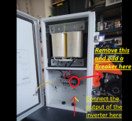
The first one is a new one. It's in series with the inverter. The second one is installed with a breaker in the panel and a neutral back to the neutral bus bar. Is there a better way?The second autotransformer don't need to be connected in that way...
JohnGalt1717
New Member
- Joined
- Dec 22, 2021
- Messages
- 107
You've yet to give a scientific answer as to why we're wrong. Please do enlighten us. As an electrical engineer (i.e. my knowledge comes from a full understanding of the physics, not just a US Code book and the wrote memorization of an electrician), I love to be educated whenever possible.The two of you are welcome to do whatever you choose in your own home.
But please don't recommend it to others.
People come here to learn how to do it properly and safely.
(PS: My install passed inspection by the local building enforcement and he was an electrician before code enforcement. I explained it and why and he looked at the UL sticker and agreed that was the correct and only safe way to do it and signed off.)
The two of you are welcome to do whatever you choose in your own home.
But please don't recommend it to others.
People come here to learn how to do it properly and safely.
That diagram is from growatt not from me, that's the safe way to connect it.
That's exactly the way i connect it.The first one is a new one. It's in series with the inverter. The second one is installed with a breaker in the panel and a neutral back to the neutral bus bar. Is there a better way?
timselectric
If I can do it, you can do it.
- Joined
- Feb 5, 2022
- Messages
- 19,934
Just read this thread. We have already hashed out everything.
Electrical Engineer? You should be able to figure it out.
Ignore the code?
Electrical Engineer? You should be able to figure it out.
Ignore the code?
JohnGalt1717
New Member
- Joined
- Dec 22, 2021
- Messages
- 107
Again, your assertion that, if the neutral from the grid is not connected and there is no ground to the transformer, there will be an imbalance on your ground is wrong. It's very easy to test and I have and the physics doesn't add up either. You literally can't get an imbalance on L1 to L2 (or visa-versa) because any imbalance is literally like putting a resistor in a circuit. This is basic Ohm's law stuff. And if there is an imbalance for any strange reason because of bonding the panel while not connecting the grid's natural, it's going to find the shortest path to source, which because of the bonding, it's the ground wire directly from the panel to the earth. So you MIGHT in some strange case get energy on the ground wire, but it won't ever hit a circuit in your house, because NONE of those paths is the shortest path to anywhere unless you disconnect your earth and if you do that, you've by definition disconnected the bonding and have other problems. (literally every single 120V flyback converter and similar just won't work as a small example)Just read this thread. We have already hashed out everything.
Electrical Engineer? You should be able to figure it out.
Ignore the code?
And the very scenario you claim is an issue? Telsa power points actually do a direct test and have special functionality for exactly that case, and won't run if you actually have the problem you claim. Which is why Will Prowse had to hack his floating ground pack to charge his Tesla, which of course didn't go well as you'll recall. I have a Tesla power point. Guess what? It has no problem with how it's wired. So physics, an amp meter, and Tesla engineers all agree with me.
But do tell, what scenario would this occur? Because ALL of the back story in this thread that I've found has the grid's neutral hooked up and bonded to the auto-transformer neutral which will absolutely cause a disaster and then people created convoluted approaches to fix when the solution was always: Don't hook up grid neutral to anything and always derive your neutral like any other transformer from the auto-transformer even when getting powered from the grid.
timselectric
If I can do it, you can do it.
- Joined
- Feb 5, 2022
- Messages
- 19,934
You are talking about an ungrounded system. Which in battery mode is what you would have in your scenario. But in bypass mode you can't create an ungrounded system while being fed from a grounded system, if using an autotransformer. The source is the grids transformer, which is a grounded system.Again, your assertion that, if the neutral from the grid is not connected and there is no ground to the transformer, there will be an imbalance on your ground is wrong. It's very easy to test and I have and the physics doesn't add up either. You literally can't get an imbalance on L1 to L2 (or visa-versa) because any imbalance is literally like putting a resistor in a circuit. This is basic Ohm's law stuff. And if there is an imbalance for any strange reason because of bonding the panel while not connecting the grid's natural, it's going to find the shortest path to source, which because of the bonding, it's the ground wire directly from the panel to the earth. So you MIGHT in some strange case get energy on the ground wire, but it won't ever hit a circuit in your house, because NONE of those paths is the shortest path to anywhere unless you disconnect your earth and if you do that, you've by definition disconnected the bonding and have other problems. (literally every single 120V flyback converter and similar just won't work as a small example)
And the very scenario you claim is an issue? Telsa power points actually do a direct test and have special functionality for exactly that case, and won't run if you actually have the problem you claim. Which is why Will Prowse had to hack his floating ground pack to charge his Tesla, which of course didn't go well as you'll recall. I have a Tesla power point. Guess what? It has no problem with how it's wired. So physics, an amp meter, and Tesla engineers all agree with me.
But do tell, what scenario would this occur? Because ALL of the back story in this thread that I've found has the grid's neutral hooked up and bonded to the auto-transformer neutral which will absolutely cause a disaster and then people created convoluted approaches to fix when the solution was always: Don't hook up grid neutral to anything and always derive your neutral like any other transformer from the auto-transformer even when getting powered from the grid.
This would be possible with an isolation transformer. Because of the separation between primary and secondary. But the L1 and L2 being carried through the autotransformer are already part of a grounded system.
JohnGalt1717
New Member
- Joined
- Dec 22, 2021
- Messages
- 107
That’s incorrect. L1/L2 are not grounded or bonded to ground anywhere in the North American power system other than your house. The ground on a transformer on the pole is connected to the case and used to create a dead short that breaks the bar breaker on the pole with the transformer in the case of a power to ground event.You are talking about an ungrounded system. Which in battery mode is what you would have in your scenario. But in bypass mode you can't create an ungrounded system while being fed from a grounded system, if using an autotransformer. The source is the grids transformer, which is a grounded system.
This would be possible with an isolation transformer. Because of the separation between primary and secondary. But the L1 and L2 being carried through the autotransformer are already part of a grounded system.
The ONLY bonding is at your primary disconnect which is after the auto-transformer, not before.
And the only reason that’s bonded is to protect the power company’s equipment and is the cause of over 95% of all house/business electrocutions: if it wasn’t bonded than the only way you could die (other than fire) would be hot to neutral across your chest. But because of bonding at primary means of disconnect earth becomes a power path and you can die from a single hand on hot or unbalanced neutral (which you should always expect) and your feet or something else touching an earthed surface without insulation.
All other justifications given are the result of mechanisms designed to deal with the bonding and using the bonding to their advantage. As a small example, without bonding a toaster in water is vastly less of a risk because you’d have to get between the hot and neutral in the water which of course is enclosed in the toaster. Even case to ground is vastly less risk in an unbonded system because the power can’t travel on the ground because it attempts to return to its source and thus the neutral. Only if both contact the case would you have risk. (Ie the same as a DC system and by detecting any voltage at all on the ground wire in either DC or unbonded you can instantly trip instead of waiting like North American ground faults)
JohnGalt1717
New Member
- Joined
- Dec 22, 2021
- Messages
- 107
And I might add you’re creating the risk of a short if the neutral does become unbalanced on either side and carries power because when you’re not connected to the grid you just put 240v through a 120v circuit best case and if they’re out of phase, you just created a complete cluster because of the harmonics you created from two power sources out of phase on the same wire. Why? Because the neutral from the grid that’s also indirectly connected to other houses on the same transformer can be carrying power at the phase of the grid and your auto transformer is carrying the unbalanced between the two phases at the phase of your inverters that aren’t synced to the grid. (Growatts do not sync, they hard transfer with a momentary disconnect which is why they’re not grid tie).You are wrong. Only if you connect the neutrals (from grid and the autotransformers) is the only way that they are in the same grounded system.
And even if your side is entirely balanced, if the grid side isn’t you’ll still get the same problem just not quite as bad until the second you draw from the auto transformer.
timselectric
If I can do it, you can do it.
- Joined
- Feb 5, 2022
- Messages
- 19,934
You're not going to get it. Your understanding of the US electrical system is too far gone.
I'm just wasting my time here.
I wish you good luck in life.
I'm just wasting my time here.
I wish you good luck in life.
JohnGalt1717
New Member
- Joined
- Dec 22, 2021
- Messages
- 107
?. Still haven’t heard any evidence of your claims. At all anywhere. And yes I’ve read essentially all of this thread.You're not going to get it. Your understanding of the US electrical system is too far gone.
I'm just wasting my time here.
I wish you good luck in life.
JohnGalt1717
New Member
- Joined
- Dec 22, 2021
- Messages
- 107
PS: you can easily test this with 12vac on an oscilloscope so you don’t do to much damage: generate 12vac from two sources, use a center tapped transformer (which is trivial to make) on each and bond the center taps.
Then put a resister from l1 to neutral on one of them.
Look at the oscilloscope. You’ll see wave interference because the two sources are out of phase.
Now bond those neutrals to an earth connection. You’ll see no difference other than now you’ll be able to get a shock from l1 to earth when you couldn’t before.
Now, instead, disconnect the neutral entirely between the two and hooked up both sources to the ends of the single transformer. Turn off one of the sources. Put a probe on the other one that is still connected just off (with a grow watt the physical connection is also removed with relays). You’ll find absolutely 0 voltage ever on that side because power always returns to its source and if there is no draw there is no power path.
Now switch off the source you have on and turn on the other side.
Again you’ll see nothing on the source that’s off.
And at no time, bonded or unbonded will you have any excess amperage on neutral or ground that you don’t have if you don’t completely physically disconnect the two systems and run them isolated.
As long as you never attach the neutral from the grid source to the neutral generated from the auto transformer there is no difference beteeen the grid’s 240 and the inverter 240. They’re literally identical and every way: they’re a full wave 240 rms sine wave at 60 hz. And the auto transformer behaves identically whether the source of that sine wave is grid or the inverter because NEITHER is bonded anywhere other than your personal primary means of disconnect. Ie the panel your inverter and grid is feeding into. 120v off of a center tap is just half the potential because of the winding, and this half the voltage. It’s still a full sine wave. It doesn’t magically imbue your 240v l1/l2 with special properties. If you don’t connect the neutral to a panel the only difference between it and a European system is that the European system would then have l2 labeled neutral and it would be earth bonded for the reasons I outlined above.
And again, you can easily test my assertions: generate 12vac so you don’t hurt yourself and then connect one leg to an earth bar. You’ll note nothing blows up. No power travels on the earth unless it gets hit by lightening or there is a case fault etc.
But you know what would cause a short? Bond both l2 AND the center tapped neutral to earth. (Or two separate derived neutrals to earth that are both carrying amperage because of an imbalance)
If you think there’s a difference, by all means tell me and the rest of us. I’m happy to eat it if I’m wrong because it isn’t about me being right, it’s about truth and facts.
And by tell us, draw the circuit that you think would cause what you claim and I’ll hook it up and report back the results of whatever you tell me to measure to the group. This is straight forward to test because it’s trivial to craste low voltage versions of the US grid. In fact Tesla himself, when he designed it, did exactly that.
But again, you’ve provided no evidence of your assertion at all. Nor has anyone else in here for that matter.
Hedges
I See Electromagnetic Fields!
- Joined
- Mar 28, 2020
- Messages
- 21,565
You've yet to give a scientific answer as to why we're wrong. Please do enlighten us. As an electrical engineer (i.e. my knowledge comes from a full understanding of the physics, not just a US Code book and the wrote memorization of an electrician), I love to be educated whenever possible.
(PS: My install passed inspection by the local building enforcement and he was an electrician before code enforcement. I explained it and why and he looked at the UL sticker and agreed that was the correct and only safe way to do it and signed off.)
Show a schematic of how your system is connected, from grid to inverter to transformer to outlet, including all neutral and ground connections.
I'll see if I can find a way for you to electrocute yourself. (or to rebalance the grid shared with neighbors.)
An isolation transformer is the only way I've figured out to make it safe.
HighTechLab
AKA Dexter - CTO of Current Connected, LLC
- Joined
- Sep 23, 2019
- Messages
- 1,787
@JohnGalt1717 you need to back up and look at the bigger picture, please. Draw a diagram, visualize the whole scenario. With your knowledge, when you see it, you will get it...but just because you don't see the problem yet doesn't mean it isn't there.
Hedges
I See Electromagnetic Fields!
- Joined
- Mar 28, 2020
- Messages
- 21,565
And by tell us, draw the circuit that you think would cause what you claim and I’ll hook it up and report back the results of whatever you tell me to measure to the group. This is straight forward to test because it’s trivial to craste low voltage versions of the US grid. In fact Tesla himself, when he designed it, did exactly that.
But again, you’ve provided no evidence of your assertion at all. Nor has anyone else in here for that matter.
Haven't seen the schematic you used yet, but Signature posted one 42 pages back.
40 pages back in this thread I linked it, and described a couple issues that could arise (depending on plumbing)

Safe Grid Use of the 5000ES and transformer
@SS, Is this true? POST #23: "That's what they told me today and they stated the Chassis do not need to be grounded." https://diysolarforum.com/threads/growatt-spf-5000-es-wiring-for-0-export-need-help.28401/page-2#post-424800 Some one will get hurt.
 diysolarforum.com
HowlerMonkey
New Member
Definitely check the building/house circuits to make sure “bonding” isn’t occurring in other places.
Last edited:
12VoltInstalls
life passes by too quickly to not live in freedom
You can do things with a meter but I really like this thing 
HELP.
Almost a year later, I have the SS 5000es/us, solaredge autotransformer and 48V batteries sitting there due to all the safety concerns brought up (and down).
My goals:
Power my 240V well pump off solar, battery, utility in that priority, so that in event of grid power loss, we still have water.
Optionally, power 120V booster pump, 120V water softener, 120V heatstripe and some lights in wellhouse off the solar/battery
Current setup:
subpanel in wellhouse that is fed from a breaker in main panel 50ft away.
I know I didn’t buy the ideal choice of inverter/autotransformer. My questions are:
- Can I safely create a panel for 240V only appliances like the well pump while keeping the 120V devices connected to utility’s grid? If so, has someone already posted a diagram?
- Can I safely create a 120V panel from a separate 48V DC to AC inverter to power the 120V things in the wellhouse? or should I just buy the $583 isolation transformer Shannon posted? Btw, is there a diagram for using the 5000es/us with the isolation transformer?
Similar threads
- Replies
- 32
- Views
- 1K
- Replies
- 5
- Views
- 439
- Replies
- 4
- Views
- 318