400bird
Solar Wizard
That's good news, thanks for verifying.
Then what (where) were you measuring? Was it set to DC amps?
Then what (where) were you measuring? Was it set to DC amps?


The good controller? If so, what was your solar output displayed by the MPPT?

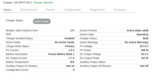
If you have a short across the PV Plus minus input of the controller and you are only measuring milliamps of current from the PV, then you would measure short circuit current from the array which would be more than a couple of amps most likely.This is one of the arrays hooked to the good unit. The other array had a similar result. Limited sunlight being that it was evenning, but the controller roared to life and started making power. 466watts. I did not measure the current meter, but math says it would be around 1.4amps. I am satisfied that both arrays are working as designed. The trouble lies in the charge controller and the short between Pv- and Pv+
View attachment 148821
Agreed, it does not add up on the surface. But it is all centered around the controller. I have proved that the arrays work as designed and all the equipment associated with them (rapid shutdown, SPDs, wiring...etc.). There is no potential between ground and any of the Pv- and Pv+ terminals, no measured path when check with an continuity meter. Something in the charge controller is clamping down on the incoming power and driving it to zero. How or why I have no idea. But what I do know is that I shouldn't measure zero ohms between Pv- and Pv+. That is the smoking gunYup, something doesn't add up here.
You measured 0.19 amps, controller shows 1.4 amps on the good controller?
Like SpongeboB Sinewave says, you should see something similar to ISC on the bad controller if the sun allows. Not 0.19 amps.
Agreed, it does not add up on the surface. But it is all centered around the controller. I have proved that the arrays work as designed and all the equipment associated with them (rapid shutdown, SPDs, wiring...etc.). There is no potential between ground and any of the Pv- and Pv+ terminals, no measured path when check with an continuity meter. Something in the charge controller is clamping down on the incoming power and driving it to zero. How or why I have no idea. But what I do know is that I shouldn't measure zero ohms between Pv- and Pv+. That is the smoking gun
TIGO rapid shutdown modules on each panel (I forget the model number). When in the off state each module outputs about 0.57 volts, so when the rapid shutdown is off the voltages add up on each array to equal a 4.7V off voltage. I know the transmitter works because when I turn power on to the unit all my surge protector lights come on and I measure voltage of the panels at around 330V. The arrays are not the issue, this is proven by the fact that the problem did not follow when switching charge controllers.What kind of rapid shutdown are you using ? There may be a PV input discharge resistor switched in ?
Are you sure that the RSD transmitter is sending an ON signal ? I know you say things are working normally but would like to know what normal actually means since we aren't there to look for ourselves.
I like a good troubleshooting challenge !
boB
Any updates on this one? Have the released the new firmware yet?This is a know bug with the eg4 bats. using the bms and SOC. Schneider Electric is going to have new firmware out in the next few days for the fix.
The fix I came up with for now is: go into the MPPT config and reset to factory. Re-setup then go into the 6848 and under battery settings turn off "SOC Control Enable" and then under grid support set "Grid Support Voltage" to 54v. When I spoke to Eric @ Schneider about this last week he told me that they are working it and will have new firmware out within days. Schneider is going to add the eg4 into the Insight BMS setup battery type for the MPPTs.
Also what is your Region Settings set to?
Hope this helps.
Neil
They released the firmware today. The firmware is 1.18 for the InsightHome-InsightFacility-Gateway.Any updates on this one? Have the released the new firmware yet?
I wonder if this MPPT Voltage Offset is their fix for the issue. I think this is new on 1.18.I was going to install it today and turn on SOC, but I think it's not going to fix the SOC using the BMS with Eg4. Did do this webinar yesterday.
Hope this helps.

I was able to find and download 1.18 the other day, but every time I tried to apply it, it said it wasn't valid. Now I see it's missing. I suspect they pulled it quietly for some reason.Firmware v1.18 is no longer listed under the firmware upgrade. I wonder if the pulled it due to issues? version 17 is the latest version that I see. Did the MPPT voltage offset work as you suspected?
https://solar.se.com/us/en/product/insighthome-and-insightfacility-edge-devices/#downloads
Firmware v1.18 is no longer listed under the firmware upgrade. I wonder if the pulled it due to issues? version 17 is the latest version that I see. Did the MPPT voltage offset work as you suspected?
https://solar.se.com/us/en/product/insighthome-and-insightfacility-edge-devices/#downloads