Yep I'll give that a goswitching of time sync will be your easiest option
")


Yep I'll give that a goswitching of time sync will be your easiest option

Your BMS has shutdown as planned..Wonder what's happened here?
View attachment 179633
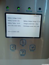
Did a full charge then full discharge, set inverter to AGM (V) with shutdown voltage at 42v as BMS was 43.2v shutdown. Screen suggest it didn't get to lower voltage but still shutdown anyway. Could the cell have hit the lower voltage shutdown (2.7v) and then recovered a bit to show the higher rate of 3ish volts? I wasn't there at the time it shutdown. 2hrs into the discharge it was showing 50%, so figured I'd check back in an hour but half hour later it was shutdown.
Now can't connect to battery!
Ah good, all normal then..........phew.Your BMS has shutdown as planned..
Tic "activate battery" in inverter and charge..
Also set your setting back to soc
I'm pretty sure your problem is the DIP switches.Hi, I've got a setup like the OP and and have a query of a similar nature some of you might be able to help with. I've got 2 8kw Sunsynk in parallel with 4 200A Seplos 280Ah battery banks connected with CAN to the inverter. On the Sunsynk battery summary it shows 370A discharge limit and 195A charge limit. The charge limit changes to whatever I set the discharge overcurrent warning to in the master BMS but this doesn't multipy in the inverter for the number of battery banks I have. This limits my charge capacity, especially in cheap overnight grid charging, to about 5kw per inverter as this figure is shared between the 2 inverters. Should the charge figure be multiplied by the inverter based on the number of batteries? If I manually set this figure higher in the master BMS it increases the number on the inverter but that leaves the master BMS vulnerable if something happens to the other banks. The discharge limit changes based on the BMS settings upto the max of 370A (2x185 max of each inverter). I've got dip switch 5 and 6 set on the master BMS for 4 banks. I must be missing something here.
the seplos and sunsynk combination actually cycle the discharge limit...Hi, I've got a setup like the OP and and have a query of a similar nature some of you might be able to help with. I've got 2 8kw Sunsynk in parallel with 4 200A Seplos 280Ah battery banks connected with CAN to the inverter. On the Sunsynk battery summary it shows 370A discharge limit and 195A charge limit. The charge limit changes to whatever I set the discharge overcurrent warning to in the master BMS but this doesn't multipy in the inverter for the number of battery banks I have. This limits my charge capacity, especially in cheap overnight grid charging, to about 5kw per inverter as this figure is shared between the 2 inverters. Should the charge figure be multiplied by the inverter based on the number of batteries? If I manually set this figure higher in the master BMS it increases the number on the inverter but that leaves the master BMS vulnerable if something happens to the other banks. The discharge limit changes based on the BMS settings upto the max of 370A (2x185 max of each inverter). I've got dip switch 5 and 6 set on the master BMS for 4 banks. I must be missing something here.

I've got 5 and 6 on the master and 1, 2, 1 and 2 on the others. This is as per the manual. With one bms connectred the inverter sets the charge at 0.5c as expected, with 2 bms it counts up and doubles as expected but adding the thried and fourth make no difference.I'm pretty sure your problem is the DIP switches.
Check the manual for the CANBUS dip switch settings for the Seplos BMS's.
How did you get this info on the chart? Specifically the charge and discharge limits. It appears as though my inverter is only 'seeing' 2 bms and setting the charge rate accordingly even though the dip switches are set to 5 and 6 on the master. I did some more testing and I noticed I have an 'alarm 0x100' on the the summary screen as per the pic I posted but I can't find what that relates to. It changes as the the inverter is establishing the charge rate. I am wondering if I need an firmware update on the bms as I am running 2 different versions. I have tried getting the latest 10E firmware from seplos so I can flash them all the same but I can't get a response from them.the seplos and sunsynk combination actually cycle the discharge limit...
in other word, it counts from highest to lowest to protect the battery and inverter stack should a battery/bms in the stack fail...
View attachment 180660
green is the discharge limit...
i bet if you look longer at that screen than 2 minutes you will see it counting down and then resetting to max
i currently have 5 batteries in maintance ( moving them into a new enclosure) , but you get the idea from above imageI
Ah. What 2 versions do you have? 10C or 10D models cannot just be flashed with 10E firmware. The "10X" denominates hardware changes, not just software.I am wondering if I need an firmware update on the bms as I am running 2 different versions.
I've got 2x 10E and 2x 10D (I used to run Voltronic inverters). When I spoke to Seplos about getting the 10E's they said they could provide the firmware so that it would all work together, which I thought they had. Indeed, it all communicates internally from pack 0-3 and the comms via CAN out of the master 10E works fine, until I discovered this issue. I suspect what I have isn't going to work how I want it to.Ah. What 2 versions do you have? 10C or 10D models cannot just be flashed with 10E firmware. The "10X" denominates hardware changes, not just software.
I found how to get it after rummaging on the desktop site. Thanks. Mine stays flat.the seplos and sunsynk combination actually cycle the discharge limit...
in other word, it counts from highest to lowest to protect the battery and inverter stack should a battery/bms in the stack fail...
View attachment 180660
green is the discharge limit...
i bet if you look longer at that screen than 2 minutes you will see it counting down and then resetting to max
i currently have 5 batteries in maintance ( moving them into a new enclosure) , but you get the idea from above image

Ahhh..... that puts me out of my misery. I shall quit trying! Thanks. If they'd told me that I could have done something different, but that's the sales guys I guess. I suppose technically they do work in that the inter bms comms seem to work but that's pointless without proper external communication. I got a quote of over $200 for the 10E now, seems to be more expensive than the v3. I could have got the v3 for £99 each on sale last week and replaced the lot. Damn.I tried to do exactly what you are wanting. I had 10D BMSs and when I bought more 10E (which they told me would work together), i worked with them for weeks to try and make it work, with a couple different firmware flashes, and ended up just buying all 10E BMSs.
v3 and v2 don't communicate...Ahhh..... that puts me out of my misery. I shall quit trying! Thanks. If they'd told me that I could have done something different, but that's the sales guys I guess. I suppose technically they do work in that the inter bms comms seem to work but that's pointless without proper external communication. I got a quote of over $200 for the 10E now, seems to be more expensive than the v3. I could have got the v3 for £99 each on sale last week and replaced the lot. Damn.
Yes, maybe they should have had said that about the previous generations too! That's my thoughts too. Just irritating that I can/could have bought 4 v3's for the price of 2 10E's. Anyone got a spare 10E they want to sell?v3 and v2 don't communicate...
plus ( and this is my personal opinion) , it's not mature enough and not worth replacing the 10E's
stay with the v2's