


You are using an out of date browser. It may not display this or other websites correctly.
You should upgrade or use an alternative browser.
You should upgrade or use an alternative browser.
Seplos CAN BUS RS485 48v 200A 8S-16S BMS
- Thread starter Firechief
- Start date


Has anyone anyone managed to change the CVL on their Seplos BMS's? I watched a video recently were Andy was unable to modify it.
I'm asking as i'm paralleling an SRNE AIO inverter/battery with my Seplos/Victron system. The SRNE settings for the Maximum Voltage Warning, and Maximum Voltage Alarm are set in stone and can not be modified.
If anyone could advise whether it is possible for the Seplos 10E be configured to match the settings below, and if so if would it be recommended it would be very much appreciated. As if not i'm probably going to have to sell the SRNE system. Thanks.
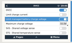
I've just noticed with the 10E, and I've read also the 10C with firmware V2.9 there is now an option in the DVCC settings of the Cerbo GX to limit the charge voltage.
Has anyone tried this? Does it work? And if so are there any unwanted consequences of doing this? Battery never reaches 100% SOC or can introduce an imbalance?
Has anyone tried this? Does it work? And if so are there any unwanted consequences of doing this? Battery never reaches 100% SOC or can introduce an imbalance?
Attachments
With the alarms enabled, the bms used to stop increasing SoC when it got to 98% (don’t remember the exact value) and then jump to 100% when one of the protections was triggered.
With the alarms disabled, the SoC doesn’t stall at a certain value, but increases as more Ah are pushed into the battery. When SoC reaches 99.5%, my inverter (Sofar ME3000SP) reads this as 100% and stops charging.
I have tried to manually increased the battery capacity and it looks like there is a lot more capacity to be filled. How do I solve this?
With the alarms enabled, the bms used to stop increasing SoC when it got to 98% (don’t remember the exact value) and then jump to 100% when one of the protections was triggered.
With the alarms disabled, the SoC doesn’t stall at a certain value, but increases as more Ah are pushed into the battery. When SoC reaches 99.5%, my inverter (Sofar ME3000SP) reads this as 100% and stops charging.
I have tried to manually increased the battery capacity and it looks like there is a lot more capacity to be filled. How do I solve this?
Perhaps the following thread may help. Stumbled across it while trying to solve my own issue.
https://www.boards.ie/discussion/2058211769/seplos-bms/p16
Just checked, nothing relevant as far as I can tellPerhaps the following thread may help. Stumbled across it while trying to solve my own issue.
https://www.boards.ie/discussion/2058211769/seplos-bms/p16
I also just noticed another thing; I have my 16 cells on two separate shelves, so cells 8 and 9 are connected by a cable rather than a busbar.
This should be mitigated by the fact that the bms has leads for …,7+,8+,9-,9+, so cell number 9 has sensing leads on both terminals. I noticed that my cell 9 was the lowest during high discharge, but the highest during charge. I tested this with a multimeter and it looks like the bms is reporting the voltage for cell 9 as the voltage difference between 8+ and 9+ instead of 9- and 9+, so it’s including the cable. It looks like the lead connected to 9- isn’t used.
This should be mitigated by the fact that the bms has leads for …,7+,8+,9-,9+, so cell number 9 has sensing leads on both terminals. I noticed that my cell 9 was the lowest during high discharge, but the highest during charge. I tested this with a multimeter and it looks like the bms is reporting the voltage for cell 9 as the voltage difference between 8+ and 9+ instead of 9- and 9+, so it’s including the cable. It looks like the lead connected to 9- isn’t used.
Sanwizard
Solar Wizard
- Joined
- Feb 2, 2021
- Messages
- 2,733
What are your min and max cell voltages? I always try to keep every connection the same to minimize cell deviation. If your cells stay out of balance and cause issues due to the setup, adding an active balancer may help.I also just noticed another thing; I have my 16 cells on two separate shelves, so cells 8 and 9 are connected by a cable rather than a busbar.
This should be mitigated by the fact that the bms has leads for …,7+,8+,9-,9+, so cell number 9 has sensing leads on both terminals. I noticed that my cell 9 was the lowest during high discharge, but the highest during charge. I tested this with a multimeter and it looks like the bms is reporting the voltage for cell 9 as the voltage difference between 8+ and 9+ instead of 9- and 9+, so it’s including the cable. It looks like the lead connected to 9- isn’t used.
I have some imbalance but I have checked the voltages with a multimeter and the bms is not considering the 9- leadWhat are your min and max cell voltages? I always try to keep every connection the same to minimize cell deviation. If your cells stay out of balance and cause issues due to the setup, adding an active balancer may help.
I’ve been looking at these parameters


According to the documentation, the first parameter is the resistance of the busbar or cable connecting cells 8 and 9; it makes sense as sometimes this is a long-ish cable with a resistance greater than the busbars, but the default value of 10mΩ seemed too big
On mine, with 65A I have a drop of about 35mV, which means a resistance of 0.53mΩ
However, I tried changing this from 10 to 0 and it doesn’t have any effect on the reported voltage of any cell under load
The parameter ‘compensation point 1 impedance’ seems to be doing something (affects cell specified under ‘compensation point 1 position’)
If I set this to 5mΩ, cell number 9 voltage is reported as
With 5A 3.335V
With 62A 3.563V (obviously it overcompensates because the resistance is luch less than 5mΩ)
If I set this to 0.5mΩ, cell number 9 voltage is reported as
With 5A 3.312V
With 62A 3.277V
Last edited:
robert272727
New Member
Hi all. Im looking on google and can find answer. Have DEYE 3 phase hybrid invertor + seplos mason with 280ah EVE cells. CAN communication and all in default. After charge to 100 percent during the day and sun power is more as for house so I have feeding to grid, even that it starts to discharge battery with around 2,5 amps until 97% SOC, it takes about 3 hours, then it charge again to 100%...and again go to 97%SOC.... In my case battery is never in state of idle....
When there is not enough power from sun it discharge battery properly to cover the house.
Please is this normal, or is this problem of deye invertor or seplos bms?
this is Im talking about - 153wats / 2,5 amps is going out from batt after fully charged.... even house don't need it...

Thanks
When there is not enough power from sun it discharge battery properly to cover the house.
Please is this normal, or is this problem of deye invertor or seplos bms?
this is Im talking about - 153wats / 2,5 amps is going out from batt after fully charged.... even house don't need it...
Thanks
Last edited:
houseofancients
Solar Wizard
this is normal.Hi all. Im looking on google and can find answer. Have DEYE 3 phase hybrid invertor + seplos mason with 280ah EVE cells. CAN communication and all in default. After charge to 100 percent during the day and sun power is more as for house so I have feeding to grid, even that it starts to discharge battery with around 2,5 amps until 97% SOC, it takes about 3 hours, then it charge again to 100%...and again go to 97%SOC.... In my case battery is never in state of idle....
When there is not enough power from sun it discharge battery properly to cover the house.
Please is this normal, or is this problem of deye invertor or seplos bms?
this is Im talking about - 153wats / 2,5 amps is going out from batt after fully charged.... even house don't need it...
View attachment 153652
Thanks
seplos does micro cycling after a full charge down tot (default) 96%.
this is to make sure cells do not stay a too high of a voltage, and it is helping the cell balancing too
Sanwizard
Solar Wizard
- Joined
- Feb 2, 2021
- Messages
- 2,733
Interesting. After finishing up the build on my racks, I finally added my 280 Masons to the busbars. The 135ah's started charging the 280's (they were added at 80%) to balance them out. After a couple hours the 280's then began charging the 135's. Back and forth. I turned off the inverters, but left the Raspberry Pi on to see what was going on. All the batteries show charging on the panel lights now. Weird. Seems the 280's are powering the Raspberry at about 34W, and the 135's are then recharging the 280's. I need to look into this in more depth.this is normal.
seplos does micro cycling after a full charge down tot (default) 96%.
this is to make sure cells do not stay a too high of a voltage, and it is helping the cell balancing too
houseofancients
Solar Wizard
i think they are balancing themselves out..Interesting. After finishing up the build on my racks, I finally added my 280 Masons to the busbars. The 135ah's started charging the 280's (they were added at 80%) to balance them out. After a couple hours the 280's then began charging the 135's. Back and forth. I turned off the inverters, but left the Raspberry Pi on to see what was going on. All the batteries show charging on the panel lights now. Weird. Seems the 280's are powering the Raspberry at about 34W, and the 135's are then recharging the 280's. I need to look into this in more depth.
Sanwizard
Solar Wizard
- Joined
- Feb 2, 2021
- Messages
- 2,733
Yup. All at 0 watts this morning except one supplying the Raspberry Pi buck converter energy.i think they are balancing themselves out..
Sanwizard
Solar Wizard
- Joined
- Feb 2, 2021
- Messages
- 2,733
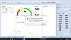
I dont want to use comms with my inverters, as I dont trust these new MPP LVX6048WP units yet. The firmware and settings are kludgy at best, and the manual is abysmal. I am using solar assistant to monitor the Seplos BMS's. (I also have a Victron shunt, but solar assistant can not take input from both the BMS and the shunt. Its one or the other.Yup. All at 0 watts this morning except one supplying the Raspberry Pi buck converter energy.
I am thinking that in order to sync all the paralleled BMS's to report the same SOC at the same voltage, I need to trip each of them to 100% by exceeding 3.65V on at least one cell in each battery.
Has anyone figured out a better way to do that yet?

houseofancients
Solar Wizard
afraid that is the only way i know how toI dont want to use comms with my inverters, as I dont trust these new MPP LVX6048WP units yet. The firmware and settings are kludgy at best, and the manual is abysmal. I am using solar assistant to monitor the Seplos BMS's. (I also have a Victron shunt, but solar assistant can not take input from both the BMS and the shunt. Its one or the other.
I am thinking that in order to sync all the paralleled BMS's to report the same SOC at the same voltage, I need to trip each of them to 100% by exceeding 3.65V on at least one cell in each battery.
Has anyone figured out a better way to do that yet?
View attachment 153930
Hi, do you think Seplose 10E can also work with Solis S6EH1P6KL? Sorry, I'm just starting to dig some information. What the S6 Solis requires is that the CAN H should be on pin4 and CAN L on pin 5. I believe RHI also follows the same pin out. I just need to figure out what battery type setting does the S6 need to be set to. Does RHI have a Pylontech battery type setting? Cause S6 has it and I'm wondering if it could work?Sparksfly30, mine is RHI inverter. This connects no problem with Seplos 10E BMS, either using GINL on BMS and user defined on inverter or SMA / AoBo.
I called Solis support yesterday after getting nowhere with raising tickets about the failure to discharge the battery once fully charged and they admitted there was an issue with battery control in the version of firmware when mine was built last year.
They did a remote firmware update and all seems to work now, so may be worth calling them.
Hi, may I ask for the board revision of your Seplos BMS? Is it 10E? ThanksHi,
What error do you get? I get a OV-Vbatt-H when it hits 100% charge, but up to now have ignored it as it clears and seems to have no effect.
What settings do you have set? I am using ginl on the bms and pylon on the inverter. All others seemed to give batt name errors.
Anyway it was working fine for me this past week, but I have lowered my settings for monomer and total pack voltages and now I get the reduced 10a charge, even below the alarm levels. My overvoltage alarm is 54v and the alarm is present even at 53.5v. I'm going to firmware upgrade to 16.06.3.
Mike
I am thinking that in order to sync all the paralleled BMS's to report the same SOC at the same voltage, I need to trip each of them to 100% by exceeding 3.65V on at least one cell in each battery.
Not necessary. First - it is no 3.65V, but some of the protection voltages. If you set it to 3.5V the BMS will disconnect the charging path to 3.5V and set the SOC to 100%.
And second - if you don't insist on 100%, but you are OK with all BMSes at 98.2% - you can get to that point without tripping the overvoltage protection. Once you reach the warning voltage thresholds the BMS will set the SOC to 98.2%. At least the 10E does it.
Sanwizard
Solar Wizard
- Joined
- Feb 2, 2021
- Messages
- 2,733
So you are setting bulk or float to 3.5? Or just cell OVP?Not necessary. First - it is no 3.65V, but some of the protection voltages. If you set it to 3.5V the BMS will disconnect the charging path to 3.5V and set the SOC to 100%.
And second - if you don't insist on 100%, but you are OK with all BMSes at 98.2% - you can get to that point without tripping the overvoltage protection. Once you reach the warning voltage thresholds the BMS will set the SOC to 98.2%. At least the 10E does it.
Here is an example:
BMS warning voltages set to 3.45V per cell and 55.2V total.
BMS protection voltages set to 3.6V per cell and 56V total. Disable the total voltage protection switch on the right.
Charger float voltage - 54.4V, charger bulk - 56V. Give it a try and share the results.
BMS warning voltages set to 3.45V per cell and 55.2V total.
BMS protection voltages set to 3.6V per cell and 56V total. Disable the total voltage protection switch on the right.
Charger float voltage - 54.4V, charger bulk - 56V. Give it a try and share the results.
Sparksfly30
New Member
i built the battery which is charged to 57.7v but the over voltage protection on seplos kicked in and inverter wont get draw because i believe the seplos has stepped on protecting battery what do i need to do about this please
houseofancients
Solar Wizard
the protection only enables charge protection, but still allows discharge..i built the battery which is charged to 57.7v but the over voltage protection on seplos kicked in and inverter wont get draw because i believe the seplos has stepped on protecting battery what do i need to do about this please
most be something else set
Similar threads
- Replies
- 26
- Views
- 1K
- Replies
- 2
- Views
- 225
- Replies
- 6
- Views
- 304
- Replies
- 22
- Views
- 2K
- Replies
- 6
- Views
- 1K