There are no settings to change once it’s connected to the bms via can; I can only change the charging power in W and the final SoC (and it gets this from the seplos bms)this is something specific to the Sofar, on my Sunsynk/Deye's there is a phase of CV , so i think you need to be looking for a setting in you sofar
You are using an out of date browser. It may not display this or other websites correctly.
You should upgrade or use an alternative browser.
You should upgrade or use an alternative browser.
Seplos CAN BUS RS485 48v 200A 8S-16S BMS
- Thread starter Firechief
- Start date
houseofancients
Solar Wizard
how the inverter handles the CV phase comes from the inverter ....There are no settings to change once it’s connected to the bms via can; I can only change the charging power in W and the final SoC (and it gets this from the seplos bms)
for instance, deye/sunsynk's load up untill the charge voltage set, then do a CV phase untill the amps reach 2% of the total amps configured before shutting down charging....
again , maybe you would have to set the correct AH of your batteries in the sofar, not sure, but i would contact sofar support to find out
Sparksfly30
New Member
Can anyone suggest any help to get seplos bms and solis sorting the battery system out
houseofancients
Solar Wizard
well, probably mossed it, but the hive mind can try..Can anyone suggest any help to get seplos bms and solis sorting the battery system out
what is your issue
Sanwizard
Solar Wizard
- Joined
- Feb 2, 2021
- Messages
- 2,733
I dont have Solis, but I am using multiple Seplos BMS packs. I am having good success by NOT using communication between the BMS's and my MPP Inverters. I am letting the BMS protect the cells, and using the User battery type with charge and float values to start and stop charging. I found that a float of 3.42 volts allows the crappy Seplos balancing to do its thing, (it defaults to 3.4v to turn on) which keeps the cells across all batteries in parallel between 3.39 and 3.42V.Can anyone suggest any help to get seplos bms and solis sorting the battery system out
I did top balance all the batteries first.
Sparksfly30
New Member
What voltage did you balance your cells to as it looks like the cells are under voltage then on ours I've only built it a couple weeks ago in the kit and didn't realise the cells would need a 3.42v charge up onI dont have Solis, but I am using multiple Seplos BMS packs. I am having good success by NOT using communication between the BMS's and my MPP Inverters. I am letting the BMS protect the cells, and using the User battery type with charge and float values to start and stop charging. I found that a float of 3.42 volts allows the crappy Seplos balancing to do its thing, (it defaults to 3.4v to turn on) which keeps the cells across all batteries in parallel between 3.39 and 3.42V.
I did top balance all the batteries first.
Sparksfly30
New Member
Solis is greyed out on the battery side. Of. The app and there's not chat aging or discharging going on at all the seplos bms says 0 ah and I think by another member I may have not balanced the cells so they may need balancing does anyone know what the max and min voltage of eve cells are to charge them to many thankswell, probably mossed it, but the hive mind can try..
what is your issue
Sanwizard
Solar Wizard
- Joined
- Feb 2, 2021
- Messages
- 2,733
For a 16s LiFePo4 pack, I place all cells in parallel, and use a CC/CV power supply to charge to 3.65V until the current goes to almost zero. It can take a LONG time, depending on the AH of the cells. You also need to constantly check the cells in case you get a runaway cell which exceeds 3.65V.What voltage did you balance your cells to as it looks like the cells are under voltage then on ours I've only built it a couple weeks ago in the kit and didn't realise the cells would need a 3.42v charge up on
Once top balanced, I then build the pack to 48V by placing the cells in series and connect them to the BMS to create a working battery.
Once connected to the inverter via a busbar, with all cables the same length, I set the inverter to bulk charge at 56V, then float at 54V (or 54.7 in my case)
Sparksfly30
New Member
Many
And did you set the cc/cv power supply to 3.65v and what current would. You start them off at to get to zero many thanks. First time. Working with this so. Don't want to just try this and that and find I make a boo booFor a 16s LiFePo4 pack, I place all cells in parallel, and use a CC/CV power supply to charge to 3.65V until the current goes to almost zero. It can take a LONG time, depending on the AH of the cells. You also need to constantly check the cells in case you get a runaway cell which exceeds 3.65V.
Once top balanced, I then build the pack to 48V by placing the cells in series and connect them to the BMS to create a working battery.
Once connected to the inverter via a busbar, with all cables the same length, I set the inverter to bulk charge at 56V, then float at 54V (or 54.7 in my case)
MatcherMike
New Member
I set my supply to 3.50v and max current and let them balance to that, before upping the voltage to 3.65 until the current drops to close to 0 just as San wizard advises. The psu will start cc and then switch to cv when it nears voltage.Many
And did you set the cc/cv power supply to 3.65v and what current would. You start them off at to get to zero many thanks. First time. Working with this so. Don't want to just try this and that and find I make a boo boo
Depending on start charge, It will take 5 - 10 days to complete! It takes ages to get to 3.5 and will then be considerably quicker to 3.65v so keep an eye on it
Kevb
New Member
Sanwizard, the issue with Solis is if you don't connect the BMS to the inverter and have valid Canbus comms, you get an error on user defined battery which prevents charge/discharge. The only option is to use Lead-Acid config on the inverter.
I tried this, but my inverter refused to discharge from the battery if it charged to over 53.5 volts.
I was hoping moving to a Seplos BMS which would talk to the inverter would fix this, but so far this is not the case.
Today I didn't get any "NO-Battery" alarms, but got the same issue (I think) as with Lead Acid config. The battery charged to 98%, then stopped charging. I wasn't there to check it reduced to 10 amps before it stopped charging, but when I got home it was not charging and had settled at 54.5 volts on the BMS (inverter reading 0.9 volts higher with no take).
However, when the sun went down, the inverter drew power from the grid instead of the battery, even though there were no warnings or alarms on the inverter or trips on the BMS.
Brum, I increased the battery over-voltage protection on the inverter and this seems to have fixed the no-battery fault, but now I need to get to the bottom of why it refuses to use a charged battery. If the inverter never gets to the point where it stops charging, there is no issue, but if it does, it seems to then refuse to discharge until the battery voltage drops to below 53.5 volts.
Sparkfly30, which Solis inverter/firmware and Seplos BMS/firmware have you got?
MatcherMike
New Member
I wonder if disabling the switch "total voltage overvoltage protection" and setting it to something much lower than "monomer overvoltage protection" x 16 would basically make the inverter keep this voltage and enter the constant voltage phase (instead of disconnecting)
It will. This is how I solved my problems with the SMA inverter. Now the BMS disconnects only if a cell goes to 3.65V. And my cells stay at ~3.5V (+- 10mV) when the total overvoltage protection kicks in. It is set to 56V.
Sparksfly30
New Member
the solis inverter is the rai_3k_4es_5g storage inverter it has firmware 110011 installedSanwizard, the issue with Solis is if you don't connect the BMS to the inverter and have valid Canbus comms, you get an error on user defined battery which prevents charge/discharge. The only option is to use Lead-Acid config on the inverter.
I tried this, but my inverter refused to discharge from the battery if it charged to over 53.5 volts.
I was hoping moving to a Seplos BMS which would talk to the inverter would fix this, but so far this is not the case.
Today I didn't get any "NO-Battery" alarms, but got the same issue (I think) as with Lead Acid config. The battery charged to 98%, then stopped charging. I wasn't there to check it reduced to 10 amps before it stopped charging, but when I got home it was not charging and had settled at 54.5 volts on the BMS (inverter reading 0.9 volts higher with no take).
However, when the sun went down, the inverter drew power from the grid instead of the battery, even though there were no warnings or alarms on the inverter or trips on the BMS.
Brum, I increased the battery over-voltage protection on the inverter and this seems to have fixed the no-battery fault, but now I need to get to the bottom of why it refuses to use a charged battery. If the inverter never gets to the point where it stops charging, there is no issue, but if it does, it seems to then refuse to discharge until the battery voltage drops to below 53.5 volts.
Sparkfly30, which Solis inverter/firmware and Seplos BMS/firmware have you got?
the seplos bms is 48200 1101 10E Sp76 16s
SEPLOS 22101040101
Do you think my cells have lost balance? They were top balanced in January, I don't recall what the imbalance was just before the end of the charge, but now it's 120mV.
During discharge the imbalance increase as SoC goes down (maybe 30mV at 80%), and at the beginning it was staying within 6mV even at 40%
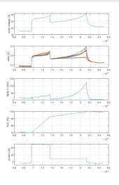
During discharge the imbalance increase as SoC goes down (maybe 30mV at 80%), and at the beginning it was staying within 6mV even at 40%

Sanwizard
Solar Wizard
- Joined
- Feb 2, 2021
- Messages
- 2,733
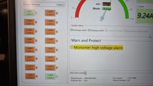
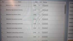
Its probably hitting the threshold on a cell while your not looking. Move the setting higher.Can anyone tell me why my bms is hitting monomer high voltage alarm short of the configured value please?
View attachment 152092
View attachment 152093
I'm continuing my experiments with the 10E BMS settings.
Yesterday I was looking in google for reverse engineered details about the BMS settings. An interesting detail that was found got confirmed today. The charging by default gets limited to 10A once the high voltage warning thresholds (for pack or for a cell) are reached. Once these are reached the charging continue in CC/CV mode with CC set to 10A and CV set to the pack high voltage protection threshold. But if the cell and pack high voltage warnings are turned off by the switches on the right in the settings dialog the charging never gets in 10A CC mode. It will stay in CV mode where the CV is being based on the pack high voltage protection threshold. I do not see much value in slowing down the charge at the end of the charge cycle, so these were disabled.
The above seems to be similar to the pack over voltage protection switch on the right of the settings dialog. If it is switched off the BMS shows the message for high voltage protection, but does not turn off the MOSFETs. If it is switched on and the pack high voltage protection voltage is reached the charging MOSFET gets disconnected.
Another thing that is still mystery is when the SOC gets at 100%. I tried to lower the pack over voltage protection from 56V to 55.2V. For several days the SOC went up to 98.2% - 98.3%. Today the battery was micro cycling for 5+ hours at around 55.2V (54.8V to 55.6V), but the SOC did not go to 100%. Looking at old data all cases where the SOC went to 100% were at pack voltage of 56V. The 10C BMS version had this hardcoded - if the voltage goes above 56V and the BMS is goes in standby mode the SOC was recalibrating to 100%. Seems that this applies for the 10E too, but I'll be able to confirm it tomorrow.
And lastly a thing I found on the internet, but I haven't confirmed yet. The interval charging that by default is 96% is likely controlling when to recharge once the SOC reaches 100%. The statements I found say, that once the SOC gets to 100% there will be no further battery charging unless the SOC falls below the interval charging threshold. If this works by disabling the charging MOSFETs I won't use it. Disabling the charging MOSFETs results in errors on inverter side in my case. But if it does not disable the MOSFETs - then I'll be setting this to 90%. I don't want to keep the battery at ~100% for half a day.
MatcherMike
New Member
Thanks for taking the time to reply.Its probably hitting the threshold on a cell while your not looking. Move the setting higher.
I don't think the settings are actually applying to the BMS. Do i need to do anything other than login as admin, and chose upload settings, then apply settings?
I changed them all back to the original settings i had which were pretty much top limit for lifepo. I rebooted my inverter, and switched off and back on the BMS. When it came back up it went back to full speed charge (not reduced 10A), however it soon stopped and 100% SOC was achieved. This was at the lower monomer levels, and total pack overvoltage - you can see the alarms in my screenshot below. You can also see however that i have upped the figures, so these alarms should not be hit. Am i missing something obvious?!
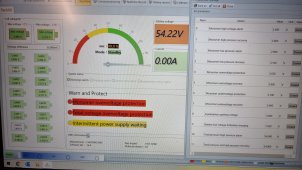
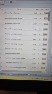
View attachment 152224
Very useful; I’ll try the constant voltage charge tomorrow; I just need to disable ‘total voltage overvoltage protection’, right?I'm continuing my experiments with the 10E BMS settings.
Yesterday I was looking in google for reverse engineered details about the BMS settings. An interesting detail that was found got confirmed today. The charging by default gets limited to 10A once the high voltage warning thresholds (for pack or for a cell) are reached. Once these are reached the charging continue in CC/CV mode with CC set to 10A and CV set to the pack high voltage protection threshold. But if the cell and pack high voltage warnings are turned off by the switches on the right in the settings dialog the charging never gets in 10A CC mode. It will stay in CV mode where the CV is being based on the pack high voltage protection threshold. I do not see much value in slowing down the charge at the end of the charge cycle, so these were disabled.
The above seems to be similar to the pack over voltage protection switch on the right of the settings dialog. If it is switched off the BMS shows the message for high voltage protection, but does not turn off the MOSFETs. If it is switched on and the pack high voltage protection voltage is reached the charging MOSFET gets disconnected.
Another thing that is still mystery is when the SOC gets at 100%. I tried to lower the pack over voltage protection from 56V to 55.2V. For several days the SOC went up to 98.2% - 98.3%. Today the battery was micro cycling for 5+ hours at around 55.2V (54.8V to 55.6V), but the SOC did not go to 100%. Looking at old data all cases where the SOC went to 100% were at pack voltage of 56V. The 10C BMS version had this hardcoded - if the voltage goes above 56V and the BMS is goes in standby mode the SOC was recalibrating to 100%. Seems that this applies for the 10E too, but I'll be able to confirm it tomorrow.
And lastly a thing I found on the internet, but I haven't confirmed yet. The interval charging that by default is 96% is likely controlling when to recharge once the SOC reaches 100%. The statements I found say, that once the SOC gets to 100% there will be no further battery charging unless the SOC falls below the interval charging threshold. If this works by disabling the charging MOSFETs I won't use it. Disabling the charging MOSFETs results in errors on inverter side in my case. But if it does not disable the MOSFETs - then I'll be setting this to 90%. I don't want to keep the battery at ~100% for half a day.
If I also disable ‘monomer over voltage protection’, will the voltage to be kept constant remain the total one or the one of the highest cell? If it’s the latter and equalisation is turned on, then this would effectively be a top balancing (i.e. the balance current would match the total pack current for the highest cell to stay at a constant voltage)
Sparksfly30
New Member
My power supply is at 3.48v and max current is pushing 5.07 amps it won't go any higher as its in cc mode at the moment
Not the protection, the warnings (alarms) for cell/pack high voltage. Warning threshold is the one that triggers 10A charging. If you disable the warnings the charging will be voltage based and the voltage is set by the pack over voltage protection setting.Very useful; I’ll try the constant voltage charge tomorrow; I just need to disable ‘total voltage overvoltage protection’, right?
If I also disable ‘monomer over voltage protection’, will the voltage to be kept constant remain the total one or the one of the highest cell? If it’s the latter and equalisation is turned on, then this would effectively be a top balancing (i.e. the balance current would match the total pack current for the highest cell to stay at a constant voltage)
Let me give the exact parameters:
The "Monomer high voltage alarm" and "Total pressure high pressure alarm" set the voltage at which the charging goes in 10A constant current mode. These can be disabled on the right and the charging will be only in CV mode. When these voltages are reached the SOC is set to 98.2%. Even if the settings on the right are disabled.
The "Total_voltage overvoltage protection" sets the charging voltage. If the protection is enabled on the right once that voltage is reached the BMS will turn off the charging MOSFETs. If it is disabled the MOSFETs will stay turned on. This is useful if an inverter is having issues due to the MOSFETs being turned off.
The "Interval charge capacity" that is expected to disable charging until SOC falls below specific value seems to be not working in my case. Most likely it needs enabled "Total_voltage overvoltage protection" to disable the charging MOSFETs and in my case this doesn't work (the SMA Sunny Island logs error whenever the charging MOSFETs are switched off).
And I've confirmed that the 100% SOC can be set without switching off the charge MOSFETs for the 10E. One attempt to charge to higher voltage (56.1V) resulted in 100% SOC being set while still charging with 10A and the voltage of the pack being 56.06V. But this had no effect on what happened after that - the charging continued the same way - with minor charge/discharge cycles after that. I was hoping that once SOC gets at 100% the BMS will ask the inverter to stop charging and ask it to start charging again once the SOC gets below the "Interval charge capacity". But I was left only with hopes.
The more I get in the BMS, the more I realize what is the problem with it - the lack of documentation. The horrible Battery Monitor translation is almost bearable. But the complexity introduced by the complex functionality and the lack of documentation is something that I would consider as a no-go if these were known before I purchased it.
So my latest settings are:
* Monomer high voltage alarm: 3.4V (alarm disabled in the settings on the right)
* Monomer overvoltage protection: 3.6V
* Total pressure high pressure alarm: 54.4V (alarm disabled in the settings on the right)
* Total voltage overvoltage protection: 54.4V (protection disabled in the settings on the right)
This way the pack charges to 3.4V per cell in CV mode set to 54.4V, does not disconnect the charging MOSFETs, but keeps the pack at 3.4V until the sun goes down and the inverter had to get energy from the battery.
The common perception seems to be that a pack kept at 100% SOC will degrade faster and this is something I would like to avoid, but there just seems to be no option for that with the Seplos BMS and the SMA Sunny Island inverter. This is why I went for 3.4V instead of 3.45V. To keep the pack floating at a bit lower voltage.
Last edited:
Sanwizard
Solar Wizard
- Joined
- Feb 2, 2021
- Messages
- 2,733
Check this out:Very useful; I’ll try the constant voltage charge tomorrow; I just need to disable ‘total voltage overvoltage protection’, right?
If I also disable ‘monomer over voltage protection’, will the voltage to be kept constant remain the total one or the one of the highest cell? If it’s the latter and equalisation is turned on, then this would effectively be a top balancing (i.e. the balance current would match the total pack current for the highest cell to stay at a constant voltage)
Do not disable that protection. This is the only thing that guarantees a cell will not go over certain voltage. This is what protects the cells from high voltage.If I also disable ‘monomer over voltage protection’
Same applies for the cell low voltage protection.
Sparksfly30
New Member
do you have a power supply link of a particular make or are they all much of a muchnessI set my supply to 3.50v and max current and let them balance to that, before upping the voltage to 3.65 until the current drops to close to 0 just as San wizard advises. The psu will start cc and then switch to cv when it nears voltage.
Depending on start charge, It will take 5 - 10 days to complete! It takes ages to get to 3.5 and will then be considerably quicker to 3.65v so keep an eye on it
Similar threads
- Replies
- 26
- Views
- 928
- Replies
- 2
- Views
- 223
- Replies
- 6
- Views
- 278
- Replies
- 22
- Views
- 2K
- Replies
- 6
- Views
- 1K


