diy solar

diy solar

Seplos CAN BUS RS485 48v 200A 8S-16S BMS

And an update with the above settings.

The battery was charging at full speed (3kW, this is what the inverter can supply) until the 3.45V cell/55.2V battery warning voltages were reached. After that the current dropped to 10A and charging continued in CC mode till the battery voltage got to 56V. Then it seems to go in CV charge mode for 12-13 minutes, the current dropped to almost zero and the SOC jumped from 98.5% to 100%.

So to me the charging algorithm seems to be as follows:
1) Charge at full speed until monomer and total pressure warning voltages are reached.
2) Switch to 10A charging (CC mode) until the total pressure voltage protection is reached.
3) Switch to CV charging mode until current drops to 0. (this will likely fail if the total pressure protection is enabled).
4) Set SOC to 100%.

If the monomer pressure protection is not reached the charge MOSFETs will not be turned off. The inverter reports no errors and warnings in the log with this settings.

The CC mode from step 2 will go to micro-charge/discharge cycle mode if the cell balancing gets open. This will still slowly climb the voltages to the "total pressure protection" threshold, but due to the fact that this is happening slowly - there will be more time for the balancing to do its job.

I'll go to a few more tests to be fully sure that the above works as stated.

I'm still wandering what the "Interval charge capacity" settings do. The default is 96%. Mine is set to 99.9%. But looking at the last results I'm not sure that I need any improvements on the charging.
Interesting results. I have reservations on needing the BMS settings to make the inverter to stop charging when hitting set limits, especially when you add additional batteries. I have seven Seplos of mixed BMS versions (C and D).
I am thinking of NOT using BMS communications, and just set my inverters to below the BMS thresholds, and will use the Victron shunt to provide total SOC. I guess I like simple. It will be interesting to see cell deviation across all the batteries. I have a Raspberry Pi I will try to get working with the Seplos BMS to monitor that with Solar Assistant.
Thanks for sharing all your testing!
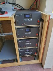
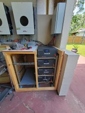
Getting there! Damn things are heavy, and trying to make this waterproof is a pain in the ass. The three larger Masons will go on the left.
 

Attachments

  • 20230529_152548.jpg
    20230529_152548.jpg
    175.1 KB · Views: 20
  • 20230529_152559.jpg
    20230529_152559.jpg
    177.6 KB · Views: 19
Really hoping someone can shed some light on this. perhaps it's nothing to worry about?

I have a 10E and a 10C paralleled, the 10E is the master running firmware v16.4, the 10C the slave on Firmware v2.8.

Prior to connecting I reset them both, set the protocol on each to Victron, connected them via RS485 and set the dip switches to 5 on the master (10E) and 1 on the slave (10C). The master can be seen by my Cerbo GX, each battery is charging and all appears to be well. However..

I'm now getting the following errors on the Slave (10C).

Get pack #1 telemetry data - Error

Get pack #1 remote connection data - Error


I haven't checked the master yet, as it's controlling my charge controllers and can't switch to RS485 until the sun has gone down (As I don't want to miss out on a single watt of solar ?) .

Has anyone experienced anything similar?


Thanks in advance.

IMG_7650.JPG
remote communication data
 
Last edited:
Really hoping someone can shed some light on this. perhaps it's nothing to worry about?

I have a 10E and a 10C paralleled, the 10E is the master running firmware v16.4, the 10C the slave on Firmware v2.8.

Prior to connecting I reset them both, set the protocol on each to Victron, connected them via RS485 and set the dip switches to 5 on the master (10C) and 1 on the slave (10E). The master can be seen by my Cerbo GX, each battery is charging and all appears to be well. However..

I'm now getting the following errors on the Slave (10E).

Get pack #1 telemetry data - Error

Get pack #1 remote connection data - Error


I haven't checked the master yet, as it's controlling my charge controllers and can't switch to RS485 until the sun has gone down (As I don't want to miss out on a single watt of solar ?) .

Has anyone experienced anything similar?


Thanks in advance.

View attachment 151357
remote communication data

My older BMS needed updating to a newer version (2.9) if anyone finds themselves in a similar situation.
 
Really hoping someone can shed some light on this. perhaps it's nothing to worry about?

I have a 10E and a 10C paralleled, the 10E is the master running firmware v16.4, the 10C the slave on Firmware v2.8.

Prior to connecting I reset them both, set the protocol on each to Victron, connected them via RS485 and set the dip switches to 5 on the master (10C) and 1 on the slave (10E). The master can be seen by my Cerbo GX, each battery is charging and all appears to be well. However..

I'm now getting the following errors on the Slave (10E).

Get pack #1 telemetry data - Error

Get pack #1 remote connection data - Error


I haven't checked the master yet, as it's controlling my charge controllers and can't switch to RS485 until the sun has gone down (As I don't want to miss out on a single watt of solar ?) .

Has anyone experienced anything similar?


Thanks in advance.

View attachment 151357
remote communication data

Question: The second sentence on your post says that the master is the 10E and the 10C is the slave, yet the next sentence says the opposite. Just to be clear, which one is the master?

I'm curious because I have two 10C's that were purchased before I found out that Seplos offered seperate RS485 and CANBUS versions. I have an MPP LV6548 and I'm encouraged to read that the 10E will communicate with the 10C, but I specifically need to use the 10E as master for the inverter interface (Pylontech via RS485) and the two 10C's as slaves.

Anyone know if this will work this way with the LV6548?
 
Sparksfly30, did you get your BMS working with your Solis inverter?

I have a Solis RHI 3.6 5G with Seplos 150A 10E BMS. They communicate no problem but I get errors on the inverter when the battery is fully charged.
I have tried using GINL on the Bms with user defined on the inverter and SMA with either user defined or AoBo on inverter.
All these give No Battery error after battery has been at 100% for a while.
I even tried Lead Acid setting without BMS but then Solis will not discharge battery if voltage is > 53 volts.
Anyone any ideas?
Thanks.
Hi,

What error do you get? I get a OV-Vbatt-H when it hits 100% charge, but up to now have ignored it as it clears and seems to have no effect.

What settings do you have set? I am using ginl on the bms and pylon on the inverter. All others seemed to give batt name errors.

Anyway it was working fine for me this past week, but I have lowered my settings for monomer and total pack voltages and now I get the reduced 10a charge, even below the alarm levels. My overvoltage alarm is 54v and the alarm is present even at 53.5v. I'm going to firmware upgrade to 16.06.3.

Mike
 
Inverter alarm = NO BATTERY

Even though the inverter shows BMS status is normal and it shows correct battery voltage.
The inverter continues to supply solar power but does not recover from this and allow battery draw without complete reset.

Not at home now. I will post settings later.
 
Question: The second sentence on your post says that the master is the 10E and the 10C is the slave, yet the next sentence says the opposite. Just to be clear, which one is the master?

I'm curious because I have two 10C's that were purchased before I found out that Seplos offered seperate RS485 and CANBUS versions. I have an MPP LV6548 and I'm encouraged to read that the 10E will communicate with the 10C, but I specifically need to use the 10E as master for the inverter interface (Pylontech via RS485) and the two 10C's as slaves.

Anyone know if this will work this way with the LV6548?

Sorry typo. now edited. The older 10C is the slave, 10E is the master.
 
You dont really need communication for your system to work. Use user defined, and make sure your settings in the inverter for battery charge/discharge are to your needs. I use 56V as bulk charge and 54V as float. 48V for cutoff. With just the black and red battery cables connected, your inverter should show voltage. Use a multimeter to confirm.
hi thanks for the info have you got the solis inverter rai version and is this how yours works sorry its taken a bit to get back in touch ive only just read your reply been busy at work
 
All these give No Battery error after battery has been at 100% for a while.

Here is one. At 100% the overvoltage protection kicks in and disconnects the charge path. The inverter detects this as an error and this results in the "No Battery" error.

How to fix it - like I did with my SMA Sunny Boy inverter. It was logging errors once the overvoltage protection disconnected the charge path. This was resulting in the inverter charging voltage jumping above a specific threshold and this was triggering an error on the inverter side. The following settings solved the problem:
* monomer high voltage warning/recovery - 3.45/3.35
* monomer overvoltage protection/recovery - 3.65/3.45
* total pressure high voltage warning/recovery - 55.2/53.6
* total pressure overvoltage protection/recovery - 56/53.6
* and the most important one - on the right side with the switches disable the "total overvoltage protection" and keep only the "monomer overvoltage protection".

How this helped - once the monomer high voltage warning and total pressure high voltage warning kick in the battery goes into CC/CV charging mode. This happens when the battery voltage gets above 55.2V and each cell is above 3.45V. Once this happens the BMS limits the current and enters the CC/CV charging phase. In that phase, the voltage is limited by the total pressure overvoltage protection (56V), and the current is limited at 10A. Once the 56V is reached and the current drops to about zero the SOC gets to 100% and the charging cycle is completed. The monomer overvoltage protection threshold of 3.65V for a cell is not yet reached and the battery charge path does not get disconnected. The inverter still sees the battery and hence no error is generated.

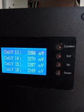
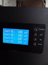
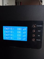
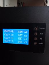
Your cells should be balanced for the above to work. Otherwise, the monomer overvoltage protection of 3.65V for a cell may be reached before the 3.5V per all cells. In that case, the charge path will be disconnected and the same error will be observed. Mine are pretty balanced - at 3.5V / 56V the voltage difference is below 0.01V (from 3.497V to 3.506V in today's charging cycle).

It is a pity that Seplos does not provide documentation about what each parameter stands for. English translation on the labels is crap and I had to partially reverse-engineer what gets the SOC at 100%.
 
Many thanks for the detailed response.
Cells are well balanced, rarely more than 3mV difference as I have an active balancer.
I will give those settings a go and report back.

I did wonder whether the BMS was cutting the charge path, so I reduced the voltage settings and reconnected my lead-acid pack in parallel with the LFP battery, so there would always be a closed circuit, but I still got a couple of No-Battery alarms yesterday evening even though the LFP only got to 96% SoC.
 
As I suspected, this didn’t fix the issue.
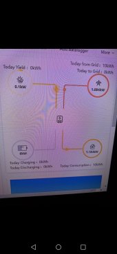
I also observed some strange behaviour on the inverter, once the SoC went above 90% the charge current was cycling from zero slowly up to 19 amps, the dropping instantly to zero and starting again.
As the SoC increased, the charge current at which it dropped back to zero reduced so that at 98% SoC it was cycling up to about 6 amps.
The inverter finally tripped on No-Battery after about 2 hours at 98% SoC and battery voltage at 55.0 volts measured by BMS, so it never got anywhere near monomer or total voltage protection.

I’m not convinced the Seplos is sending all values to the correct addresses. The total voltage overprotection in BMS seems to be writing to the Absorption voltage in the inverter.
 
Last edited:
I’m not convinced the Seplos is sending all values to the correct addresses. The total voltage overprotection in BMS seems to be writing to the Absorption voltage in the inverter.

Yes, this is kind if identical to what I stated above. The total voltage overvoltage protection sets the voltage for the CC/CV charging phase. Or in other words - the absorption voltage.

I also observed some strange behaviour on the inverter, once the SoC went above 90% the charge current was cycling from zero slowly up to 19 amps, the dropping instantly to zero and starting again.
This looks a bit like the micro cycling, but not exactly.

The BMS keeps logs. Can you check them and post them here? Use the Battery Monitor tool to get them. Not sure if you can do that through the Bluetooth interface.
 
I have a Solis RHI 3.6 5G with Seplos 150A 10E BMS. They communicate no problem but I get errors on the inverter when the battery is fully charged.

Looking for more details on the Seplos BMS functions and I found something that may be useful to you - https://www.boards.ie/discussion/comment/119273016/#Comment_119273016 . Others had the same problem and it seems like there is a custom firmware for solving it.

This may be for older BMS, but the thread is worth checking.
 
when people are talking about balancing the cells is that to charge them fully and all of the cells charged to approx same percentage and voltage
 
Here is one. At 100% the overvoltage protection kicks in and disconnects the charge path. The inverter detects this as an error and this results in the "No Battery" error.

How to fix it - like I did with my SMA Sunny Boy inverter. It was logging errors once the overvoltage protection disconnected the charge path. This was resulting in the inverter charging voltage jumping above a specific threshold and this was triggering an error on the inverter side. The following settings solved the problem:
* monomer high voltage warning/recovery - 3.45/3.35
* monomer overvoltage protection/recovery - 3.65/3.45
* total pressure high voltage warning/recovery - 55.2/53.6
* total pressure overvoltage protection/recovery - 56/53.6
* and the most important one - on the right side with the switches disable the "total overvoltage protection" and keep only the "monomer overvoltage protection".

How this helped - once the monomer high voltage warning and total pressure high voltage warning kick in the battery goes into CC/CV charging mode. This happens when the battery voltage gets above 55.2V and each cell is above 3.45V. Once this happens the BMS limits the current and enters the CC/CV charging phase. In that phase, the voltage is limited by the total pressure overvoltage protection (56V), and the current is limited at 10A. Once the 56V is reached and the current drops to about zero the SOC gets to 100% and the charging cycle is completed. The monomer overvoltage protection threshold of 3.65V for a cell is not yet reached and the battery charge path does not get disconnected. The inverter still sees the battery and hence no error is generated.

Your cells should be balanced for the above to work. Otherwise, the monomer overvoltage protection of 3.65V for a cell may be reached before the 3.5V per all cells. In that case, the charge path will be disconnected and the same error will be observed. Mine are pretty balanced - at 3.5V / 56V the voltage difference is below 0.01V (from 3.497V to 3.506V in today's charging cycle).

It is a pity that Seplos does not provide documentation about what each parameter stands for. English translation on the labels is crap and I had to partially reverse-engineer what gets the SOC at 100%.

This is interesting; I am using a Sofar ME3000SP, which charges at 50A (or 10A when monomer overvoltage alarm is hit), but doesn't do any CV phase, because as soon as "monomer over voltage protection" or "total voltage overvoltage protection" are hit, it stops charging
I wonder if disabling the switch "total voltage overvoltage protection" and setting it to something much lower than "monomer overvoltage protection" x 16 would basically make the inverter keep this voltage and enter the constant voltage phase (instead of disconnecting)
this is something specific to the Sofar, on my Sunsynk/Deye's there is a phase of CV , so i think you need to be looking for a setting in you sofar
 

diy solar

diy solar
Back
Top