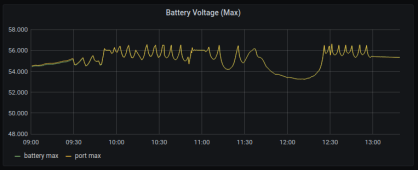
I've correlated the inverter logs with the BMS logs. Voltage matches pretty closely with minor deviation in all cases except the voltage spikes. There is also port voltage log, so I'll be able to trace the issue in more detail by collecting logs at the proper time. The only warnings shown in the logs correlated with the problem are:
- Monomer high voltage alarm
- Total_voltage overvoltage protection
- Intermittent power supply waiting
Next steps:
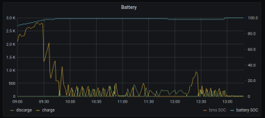
1) Check if the issue persists and the inverter sees a higher than the battery voltage. Such are observed in the existing logs a few seconds after the high voltage protection of the BMS kicks in. In all cases, the inverter says that it is discharging, not charging. And this happens almost everytime when the BMS hits 100% SOC.
2) If issues are ongoing - modify the WiFi to RS485 bridge that I've created to collect data on second bases. Push that data for analysis. Once I'm able to check these against each other I'll know what's going on.