You are using an out of date browser. It may not display this or other websites correctly.
You should upgrade or use an alternative browser.
You should upgrade or use an alternative browser.
Seplos CAN BUS RS485 48v 200A 8S-16S BMS
- Thread starter Firechief
- Start date
Thanks Neil, do you have a picture at all showing the busbars connected to the board ?The v3 connects only to the negative side of the battery and there is a small screw terminal on the bms for a positive feed (B+)
The positive from the battery feeds directly via fuse to the invertorView attachment 189046
Neil H
New Member
You fitting it to a Mason?Thanks Neil, do you have a picture at all showing the busbars connected to the board ?
Horizontal or vertical ?
Mason horizontal.You fitting it to a Mason?
Horizontal or vertical ?
Neil H
New Member
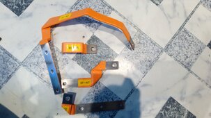
That looks like the V2 kitThese are the busbars that came with it.
Radio silence from Seplos so far. ?
And awaiting a reply from Frogstar.
View attachment 189050
So I have a v3 board with v2 busbars ? ?That looks like the V2 kit
Neil H
New Member
See belowe
Last edited:
Neil H
New Member
So N2 goes from B1 to battery neg looking at the BMS it will go to the left and up
N3 will go to the left side of the fuse from P-
N5 from fuse to Neg outpout
N7 from battery to poss output
PS the neg / positive outputs are the other way round to V2
N3 will go to the left side of the fuse from P-
N5 from fuse to Neg outpout
N7 from battery to poss output
PS the neg / positive outputs are the other way round to V2
Neil H
New Member
hope that helps
Neil H
New Member
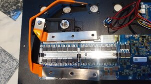
That's right they do need a bit of bending also put the fuse in 1stThanks for taking the time Neil, much appreciated, but that doesn't look right either.
N2 won't reach the battery from there and N3/N5 wouldn't fit either .
I'm not convinced I even have the correct busbars.
View attachment 189065
Last edited:
Neil H
New Member
N2 (B1) goes the other way (points to the right
sorry
sorry
Actually Neil, that's beginning to make more sense and I think you could be right.
I'll maybe hang fire till I get a reply from Frogstar or Seplos though for some official instructions.
Don't want to end up with a £2k brick. ?
I'll maybe hang fire till I get a reply from Frogstar or Seplos though for some official instructions.
Don't want to end up with a £2k brick. ?
Last edited:
I'll have a go at connecting the busbars this afternoon without connecting up to the battery to see if they fit.N2 (B1) goes the other way (points to the right
sorry
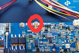
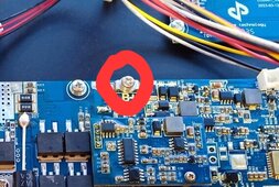
Do you reckon then that nothing actually connects to the small B+ screw ?
Or is it maybe something to do with the active balance board ?

Last edited:
houseofancients
Solar Wizard
it isThat looks like the V2 kit
Neil H
New Member
this is the positive supply to the BMS as the other main leads are only negativeI'll have a go at connecting the busbars this afternoon without connecting up to the battery to see if they fit.
Do you reckon then that nothing actually connects to the small B+ screw ?
Or is it maybe something to do with the active balance board ?
View attachment 189066
should have a short red lead with a large round terminal on one end and a small on the other this connects to the positive on the batteries
Neil H
New Member
its notit is
Yes, there is. About 48cm long. ?this is the positive supply to the BMS as the other main leads are only negative
should have a short red lead with a large round terminal on one end and a small on the other this connects to the positive on the batteries
So presumably, the BMS negative supply goes to B- via the busbars ?
Therefore P- is power negative and B- is battery negative ?
Similar threads
- Replies
- 21
- Views
- 1K
- Replies
- 6
- Views
- 1K
- Replies
- 17
- Views
- 898
- Replies
- 2
- Views
- 418
- Replies
- 1
- Views
- 212


