diy solar

diy solar

Setting up jkpb1a16s10p BMS and have questions.

D. Abineri

New Member
Joined
Jun 25, 2021
Messages
306
Location
Blacksburg, VA
This unit comes with a small plug that can be plugged onto the board and has 4 green wires tied to a single ring terminal, a red wire nd a black wire. Thee are thin wires, intended for low loads or data signals.

Where do these wires go? What are they connected to? What are they for?

Thanks.
 
Post a pic, but I'm betting they are for a heating option.

ETA: Yep.

 
Last edited:
#40 Fan you are exactly correct, that is the cable I was describing although my bms does not have the H designation.

But, I am hopeful that you can help with a couple of other issues that I am having getting bms up and running. It sounds as if you have already gone throgh these with your setup perhaps.
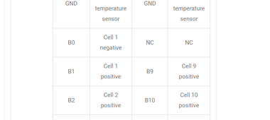
I have the unit connected but I have a flashing red light on the bms and an alarm light on the communication board. Also the android app shows that is is not reading the voltage of Cell and indicates that cell count (16) is not correct. So the BMS is not running yet. The B1 connection is certainly there. I note on the connector of the cell data lines that the connecton to B0 is a N/C but on my previous bms, thi was the negative of B1.

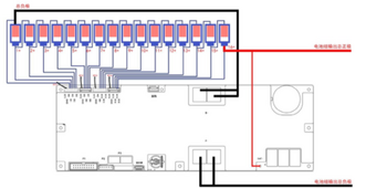
I have the battery negative to B- and I have P- connected to the inverter. And there is a single line from the bms to B+.

What can oyu tell me about this situation from your experience? My cells are not bing charged right now to it is important that I get this up and running as soon as I can.

Thanks for anything you can offer regarding this situation.
Dave
 
I'm still in the reading and learning phase. I don't own anything.

Did you check each wire at the BMS end with a voltmeter to confirm you have voltage incrementing from cell 1 to cell 16?

Do you have an install manual you can link me to?
 
The B1 connection is certainly there. I note on the connector of the cell data lines that the connecton to B0 is a N/C but on my previous bms, thi was the negative of B1.

I'm not sure what you mean by this, but the first wire (it appears to be called "GND"), should be connected to the negative terminal of the first cell. For 16S, there should be 17 sense wires and the power wire.
 
I have the unit connected but I have a flashing red light on the bms and an alarm light on the communication board. Also the android app shows that is is not reading the voltage of Cell and indicates that cell count (16) is not correct. So the BMS is not running yet. The B1 connection is certainly there. I note on the connector of the cell data lines that the connecton to B0 is a N/C but on my previous bms, thi was the negative of B1.
You need to use a DVM (voltage meter) to check the sense leads and find the faulty connection. Unplug the sense wire harness from the BMS and one by one, test the voltage on each wire by carefully pointing the DVM probe onto the correct terminal in the harness. It should give you the cell voltage of #1 cell then #1 and #2 added together, then #'s 1, 2 and 3, etc. These numbers have to continually show the voltage increase of each added battery. Of course the #17 + wire is just the power wire for the BMS.
You may find a problem connection in doing this test. You may need to cut and recrimp another terminal on the end.
 
I'm still in the reading and learning phase. I don't own anything.

Did you check each wire at the BMS end with a voltmeter to confirm you have voltage incrementing from cell 1 to cell 16?

Do you have an install manual you can link me to?
Thanks for staying with me on this. The only manual I have found is this one https://www.jkbms.com/product/jk-pb1a16s10p-jk-pb1a16s-10p/.
I have doble checked the cell sensor wires with a voltmeter and they do increment correctly by about 3+ volts.
In the manual uner 9 INTERFACE DEFINITION B0 is NOT CONNECTED and there is no wire in tht position on he plug. So it must be getting a ground from somewhere else?? The support from the manufacturer is useless and basically non existant.

Thanks for any ideas you have on this.
 
You need to use a DVM (voltage meter) to check the sense leads and find the faulty connection. Unplug the sense wire harness from the BMS and one by one, test the voltage on each wire by carefully pointing the DVM probe onto the correct terminal in the harness. It should give you the cell voltage of #1 cell then #1 and #2 added together, then #'s 1, 2 and 3, etc. These numbers have to continually show the voltage increase of each added battery. Of course the #17 + wire is just the power wire for the BMS.
You may find a problem connection in doing this test. You may need to cut and recrimp another terminal on the end.
Thanks for this, I have checked the voltages twice. But how do I check the B1 voltage without a B0 connection. I am used to seeing B0 as one of the connections (to battery - ) but this has no B0 connector. See the manual https://www.jkbms.com/product/jk-pb1a16s10p-jk-pb1a16s-10p/

Please let me know if you see something I am missing. Thanks.
 
Thanks for this webbbm. Look at the manual if you would https://www.jkbms.com/product/jk-pb1a16s10p-jk-pb1a16s-10p/.

There is NO CONNECTION where there would usually be B0.

I was looking at the wrong manual. You left the 'P' off of the part number in the title.

In any case, I see a connection to the negative terminal of the battery in the manual that you linked called B0:

1703779814673.png
It looks to me like that connector is a dual-row connector and the pin across from B0 is NC.

I don't know if you've found it yet, but Andy on Off-Grid Garage YouTube channel had a series of videos on the new JK BMS recently. There might be some useful information in those videos.
 
I was looking at the wrong manual. You left the 'P' off of the part number in the title.

In any case, I see a connection to the negative terminal of the battery in the manual that you linked called B0:

View attachment 185506
It looks to me like that connector is a dual-row connector and the pin across from B0 is NC.

I don't know if you've found it yet, but Andy on Off-Grid Garage YouTube channel had a series of videos on the new JK BMS recently. There might be some useful information in those videos.
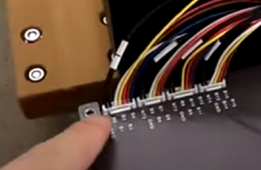
I did watch Andy but not all the details are explained. The connectors are all single row but, as you see in the manual, there is N/C (No Connection) ro pin B0. In the picture attached (not a pic) there is no metalic connector on the third position from the left. First two are temp sensor, 3 is blank nd the rest are B1,B2,B3 and B4. There is a shadow under pin 3.
 
I was looking at the wrong manual. You left the 'P' off of the part number in the title.

In any case, I see a connection to the negative terminal of the battery in the manual that you linked called B0:

View attachment 185506
It looks to me like that connector is a dual-row connector and the pin across from B0 is NC.

I don't know if you've found it yet, but Andy on Off-Grid Garage YouTube channel had a series of videos on the new JK BMS recently. There might be some useful information in those videos.
It is strange that they label the 3rd pin as B0 cell 1 negative but there i no wire in thaat position??
 
Can you post a picture of what you're seeing? This nearly useless picture from the online manual shows a wire to the negative of the first battery:

1703807670152.png
 
I did watch Andy but not all the details are explained. The connectors are all single row but, as you see in the manual, there is N/C (No Connection) ro pin B0. In the picture attached (not a pic) there is no metalic connector on the third position from the left. First two are temp sensor, 3 is blank nd the rest are B1,B2,B3 and B4. There is a shadow under pin 3.
Just measured all the cell sensor voltages again. I measured from the Battery negative (even though there is no B0 pin) and they are all correct. That is why I say that it be picking up B- internally for the missing B0 wire.
Can you post a picture of what you're seeing? This nearly useless picture from the online manual shows a wire to the negative of the first battery:

View attachment 185576
Yes, the manual is pretty useless. That wire to B- does not exist as can me seed in the attached document. So cell 1 is not recognized.
 

Attachments

  • bms problems.pdf
    590.8 KB · Views: 12
Don't assume that the B0 pin is actually connected to battery negative. The cell voltage sense wires are almost certainly differential.

Did that cable come with the BMS? Even it was, I would try connecting that missing wire to B1 negative. If it's really not connected, it's not going to hurt anything, but I'm sure it needs to be connected.

I also went through Andy's videos, and this shows that he does have that pin connected:

1703815017856.png
 
I believe you may be correct but I am in the process of returning this item for a refund so I won't make any changes just yet. Also, as seen in my pic, than plug has no metalic contact on the 3rd position so it may be a little tricky to wire that pin to B-. Yes, the whole wiring harness came with the bms. And hy do the intructions show No Connection for the 3rd pin? Too many unknowns here until I find someone who has one. Thanks for your input, I may end up making that connection eventually.
 
Don't assume that the B0 pin is actually connected to battery negative. The cell voltage sense wires are almost certainly differential.

Did that cable come with the BMS? Even it was, I would try connecting that missing wire to B1 negative. If it's really not connected, it's not going to hurt anything, but I'm sure it needs to be connected.

I also went through Andy's videos, and this shows that he does have that pin connected:

View attachment 185613
Also, notice in your pic from Andy that the 3rd plug from the left has a NC on the 3rd pin!. I am switching the wiring between the first and third plugs so that I get a B0 c0nnection. The reason for the NC on the 3rd pin of the 3r plug is that the bms shows two connetions to B8 and only one is needed from the second plug. I am re-wiring these now and will let you know if this is the solution. The online manual is where the problem lies, it shows a NC for B0.
 
Also, notice in your pic from Andy that the 3rd plug from the left has a NC on the 3rd pin!. I am switching the wiring between the first and third plugs so that I get a B0 c0nnection. The reason for the NC on the 3rd pin of the 3r plug is that the bms shows two connetions to B8 and only one is needed from the second plug. I am re-wiring these now and will let you know if this is the solution. The online manual is where the problem lies, it shows a NC for B0.

Looks like you have found the winning solution! You can even see the missing pin on the third connector in that crappy photo.

Sorry I wasn't able to get back to you yesterday and thanks for linking the manual.
 
Back
Top